The blow unit is usually the last item confirmed on a specification sheet and the first one to appear in a rejected shipment. If the blow pin leaves a witness mark on a face the buyer inspects, or the neck will not hold a seal on the filling line, a larger clamp and a longer screw will not recover the order. Before comparing models, settle two things: where the opening is, and where a mark is allowed to sit.
The short answer: start at the neck, finish at the mark
Choose the blow unit by the neck opening and by where a mark is allowed. Needle blow enters through a small neck and suits small-mouth bottles. Top blow works from above and suits wide-mouth containers and drums. Bottom blow is chosen where the base must stay free of a mark. Confirm the pin position on the mold drawing.
Three blow units, one sealing point each
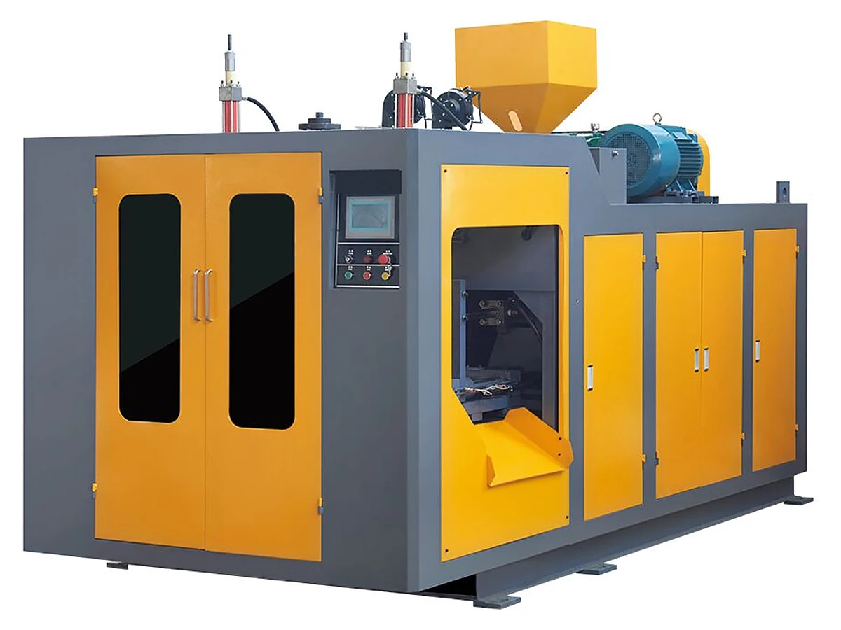
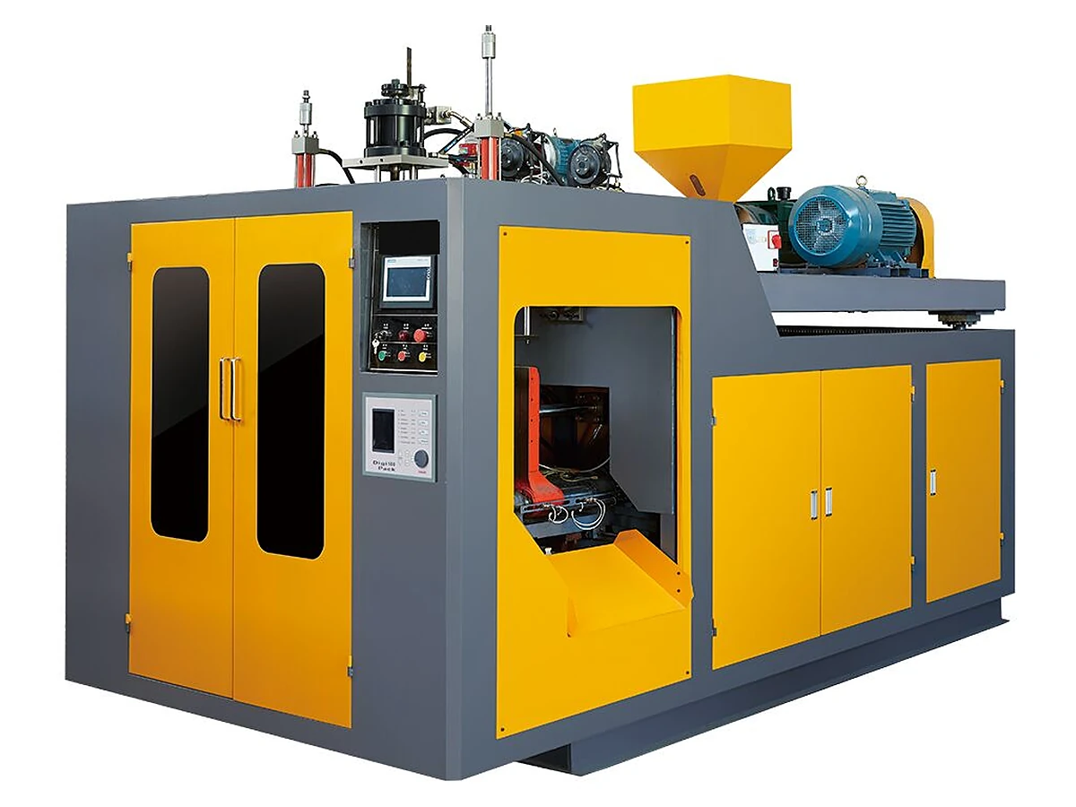
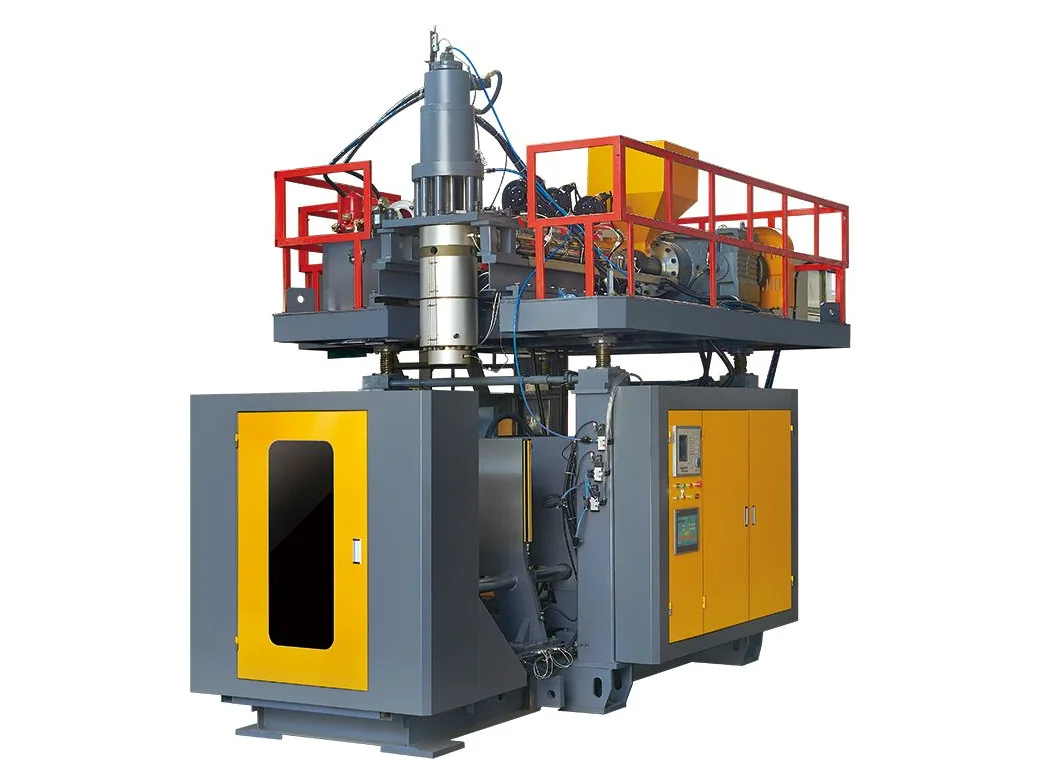
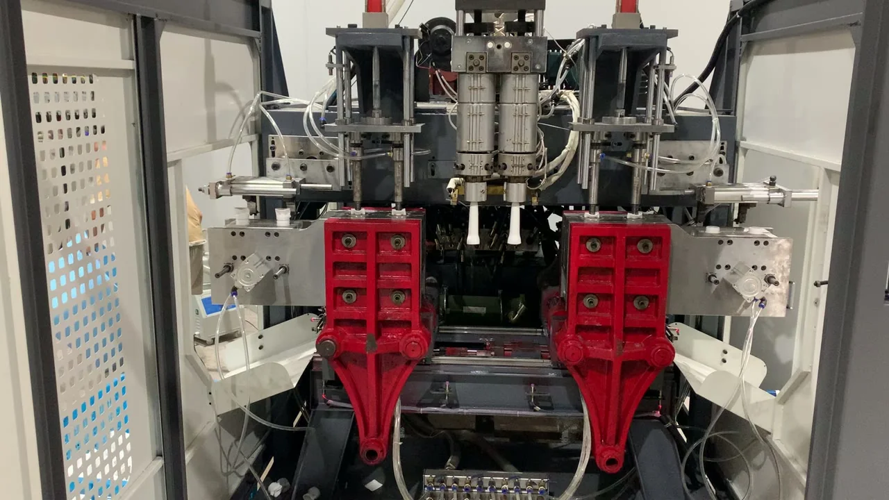
An extrusion blow molding machine can be read as three sub-systems that have to match: the die head that forms the parison, the blow unit that inflates it, and the parison thickness and length control that decides where the material sits. The blow unit is the smallest of the three, yet it owns the two features a customer checks first, the neck and the base.
- Needle blow: a slim pin enters through the neck opening, and the neck is formed and cooled around it. Neck diameter and seal quality depend on the mold and on pin condition.
- Top blow: air is delivered from above through the open mouth. Wide-mouth containers and drums gain a flat base and a fully open mouth for filling and washing.
- Bottom blow: air is delivered through the base. It is the option to discuss when a mark from the blowing side is not allowed at the bottom; the witness point has to be agreed on the drawing first.
- On all three, E-SHION configures the blow pin to the neck design and the mold rather than fitting one universal head; the drawing and a sample bottle are the reference.
The choice is not settled by clamp force or screw diameter. Those size the machine, and they still have to be checked, with clamping force covering mold projection area times blowing pressure rather than container volume. But a 10 L machine with the pin in the wrong place will still make bottles that leak at the neck.
There is also a production angle. The blow unit sits at the end of every cycle: the parison is cut, the mold closes, the pin enters, air inflates, the part cools and the mold opens. A pin that is slow to retract or leaks at its seal adds that time to every cycle, all shift, and on a multi-cavity tool the same fault repeats by the cavity count.
Which blow unit fits which container
The table below is a starting filter, not a specification. Use it to shortlist, then confirm each line against the neck drawing, the base design and the buyer's inspection standard.
| Blow unit | Where air enters | Typical container | Agree before the mold is cut |
|---|---|---|---|
| Needle blow | Through the neck opening, on a slim pin | Small-mouth bottles and jars, roughly 0.1-5 L | Pin diameter, neck seal, mark position, pin cooling |
| Top blow | From above, through the open mouth | Wide-mouth containers and open-top drums | Neck ring, top trim, calibrator clearance, handle clearance |
| Bottom blow | From below, through the base | Containers that must stay free of a top-side mark | Base pad, pin seal, trim, and who accepts the mark |
Swipe the table to see all columns →
Two rows often get mixed on a real project. A jerrycan with a wide neck but a handled body may need the pin placed where the handle will not interfere, and a wide-mouth jar with a threaded neck may still run needle blow if the neck is small enough. The drawing decides, not the product name.
What this means on a 5 L or 10 L machine
In the single-station range, the ES-5LS is listed at 100 kN clamp, a 320 x 380 mm platen, a 60-65 mm screw and 65-80 kg/h output; the ES-10LS at 110 kN, 450 x 480 mm, a 70-75 mm screw and 80-100 kg/h. Those figures size the machine. The blow unit is configured separately, to the neck and the mold, which is why two buyers on the same model can be running completely different bottles.
Output is cavities multiplied by good parts per cavity per cycle, multiplied by cycles per hour, and cycles per hour is 3600 divided by the measured cycle time. A blow unit that cools the neck well shortens the cycle. One that does not shows up first as neck ovality, a weak pinch-off or wall-thickness variation, and only later in the output figure. Measure on samples, not on the nameplate.
If you are still comparing machine architecture, start withhow to choose an extrusion blow molding machineandaccumulator versus continuous extrusion. For 5 L and 10 L containers, see thesingle-station 0-16 L rangeand thedouble-station 0-16 L range. Two more that come up at this stage:5 L versus 10 L jerrycan machinesandcontainer labelling by market.
What to send for a quotation
- Bottle drawing with the neck finish, thread or snap specification, and the base design.
- Container volume, material and layer structure, single layer or multi-layer with EVOH or regrind.
- Where the blow pin mark may sit, and which faces the customer inspects.
- Target output per hour and the shift pattern, so cavities and station count can be sized.
- Mold quantity, and whether an existing mold must be reused with its current pin and neck details.
- Destination country, power supply, and any auxiliary equipment already on site.
Source: E-SHION product data. Specifications are subject to change without notice; customization is available.
This guide is written for production and procurement decisions. It uses published figures where available and avoids unverified performance claims.