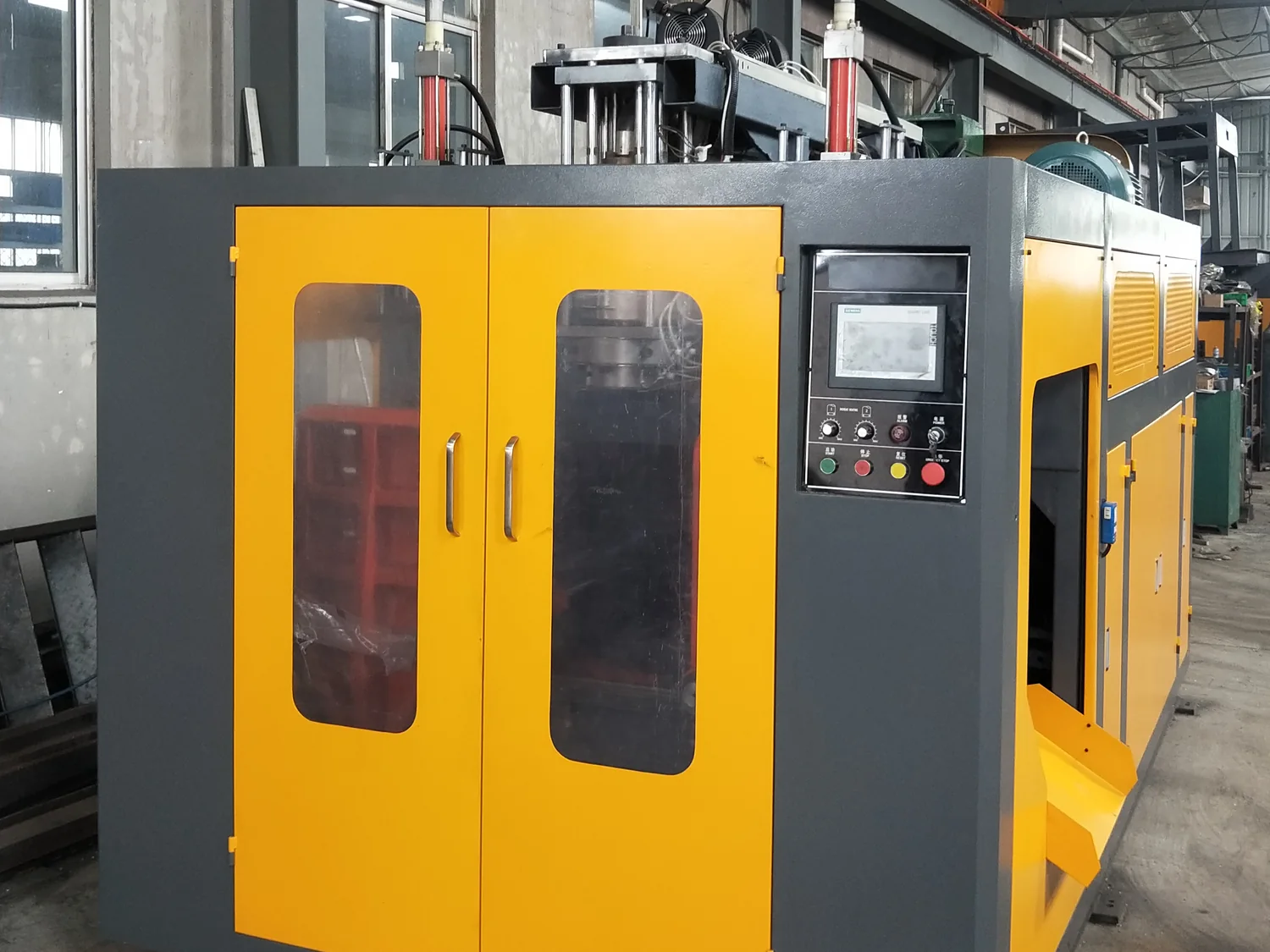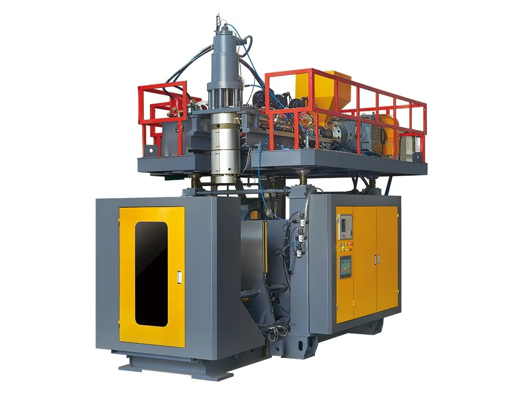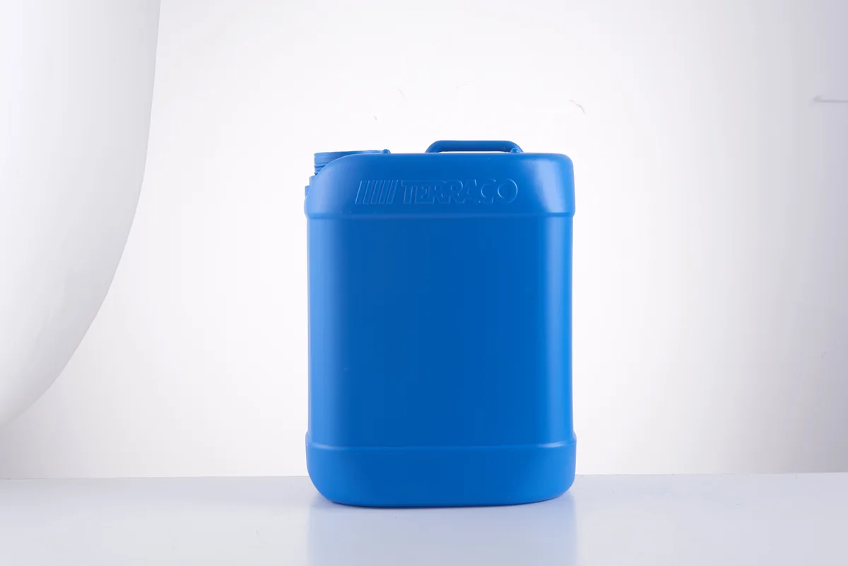
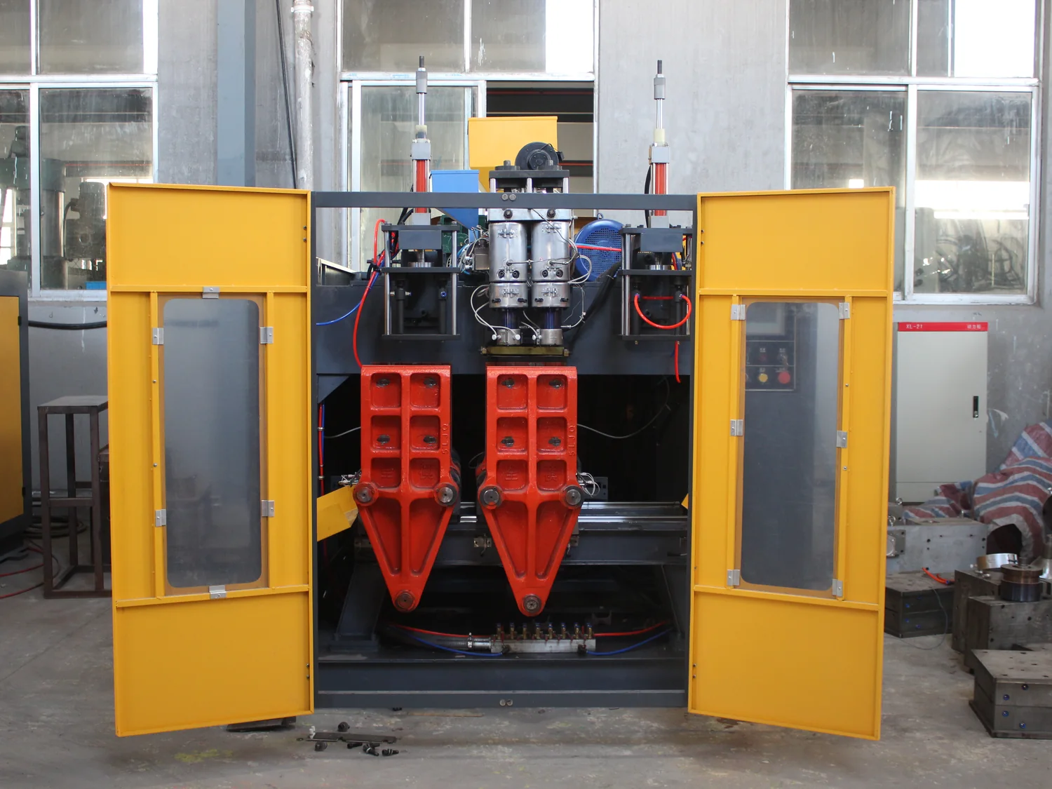
Most machine comparisons start with maximum volume. That is the least useful number on its own. A 5 L bottle with a handle, a 5 L wide-mouth jar and a 5 L jerrycan can require different mold sizes, platen spacing and take-out arrangements — even though the catalog may list all three under the same maximum capacity.
1. Fix the finished part first
Write down the body diameter, overall height, neck finish, handle, part weight, wall-thickness range, material grade and any barrier or recycled-content requirement. If you have a drawing or 3D file, use it. A nominal capacity is not a specification.
This step also decides whether the part belongs in the small-container range at all. A tall 16 L container can be a different project from a squat 16 L jar, because height drives the platen-spacing requirement and mold height.
2. Check the machine envelope, not just the volume
For every candidate model, compare the following fields side by side:
- Die plate size: the mold footprint must fit with room for clamping and support.
- Platen spacing: must clear the mold thickness plus the space needed to remove the part.
- Clamping force: must hold the mold closed against the blowing pressure; check it against mold projection area, not just container volume.
- Screw diameter and L/D: affect melting, output and the material range.
- Extruding capacity: the plastic throughput available to the die head, in kg/hr.
- Die-head layout and center distance: must match the cavity spacing in the mold.
The catalog's two-, three- and four-head center distances are mold-layout figures, not maximum container diameters. They are useful for a first mold-layout check; the mold designer has the final say.
3. Calculate output from the actual cycle
Finished output is not the same as extruding capacity. Use this formula:
A two-cavity mold with a measured 20-second cycle gives 180 cycles/hour and 360 theoretical parts/hour before scrap. If the verified scrap rate is 3%, the planning figure is about 349 good parts/hour. Replace the example with measured values from the actual mold, material and cooling setup.
4. Choose the station count before the cavity count
A single station is compact and easier to change over. A double station can raise output per cycle and use the extruder more intensively, but it also introduces more mold positions, more take-out coordination and a larger footprint. The right answer depends on the product mix and the number of shifts, not on a preference for 'more automation'.
5. Treat power figures correctly
Installed power is the connected load used for electrical planning. Actual power is an operating reference that changes with heating demand, material, cycle and ambient conditions. The QQ-50L, for example, lists 105–120 kW installed and 35–50 kW actual. Use the installed figure for the electrical supply and the actual figure for a first energy estimate, then measure the real machine.
6. Confirm the mold and utilities before the quotation is fixed
Mold interface, platen mounting pattern, die-head position, air supply, cooling water, voltage and take-out automation all belong in the same conversation. A machine can be technically capable and still be a poor fit if the existing mold cannot be mounted or the plant cannot supply the required air and cooling.
A simple selection sequence
- Define the container, material and annual volume.
- Estimate the mold size and cavity layout.
- Shortlist platforms by platen, platen spacing and clamping force.
- Calculate output from a measured or quoted cycle time.
- Confirm the die-head, take-out and utility plan.
- Ask for the final configuration, test scope and service terms in writing.
Source: E-SHION product catalog, pages 05–10. Specifications are subject to change without notice; customization is available.
This guide is written for production and procurement decisions. It uses catalog data where available and avoids unverified performance claims.