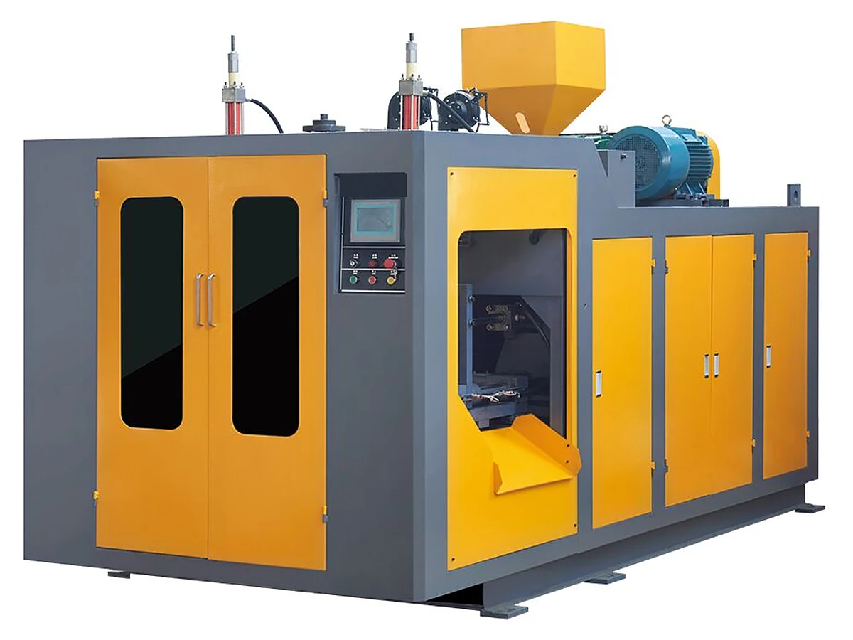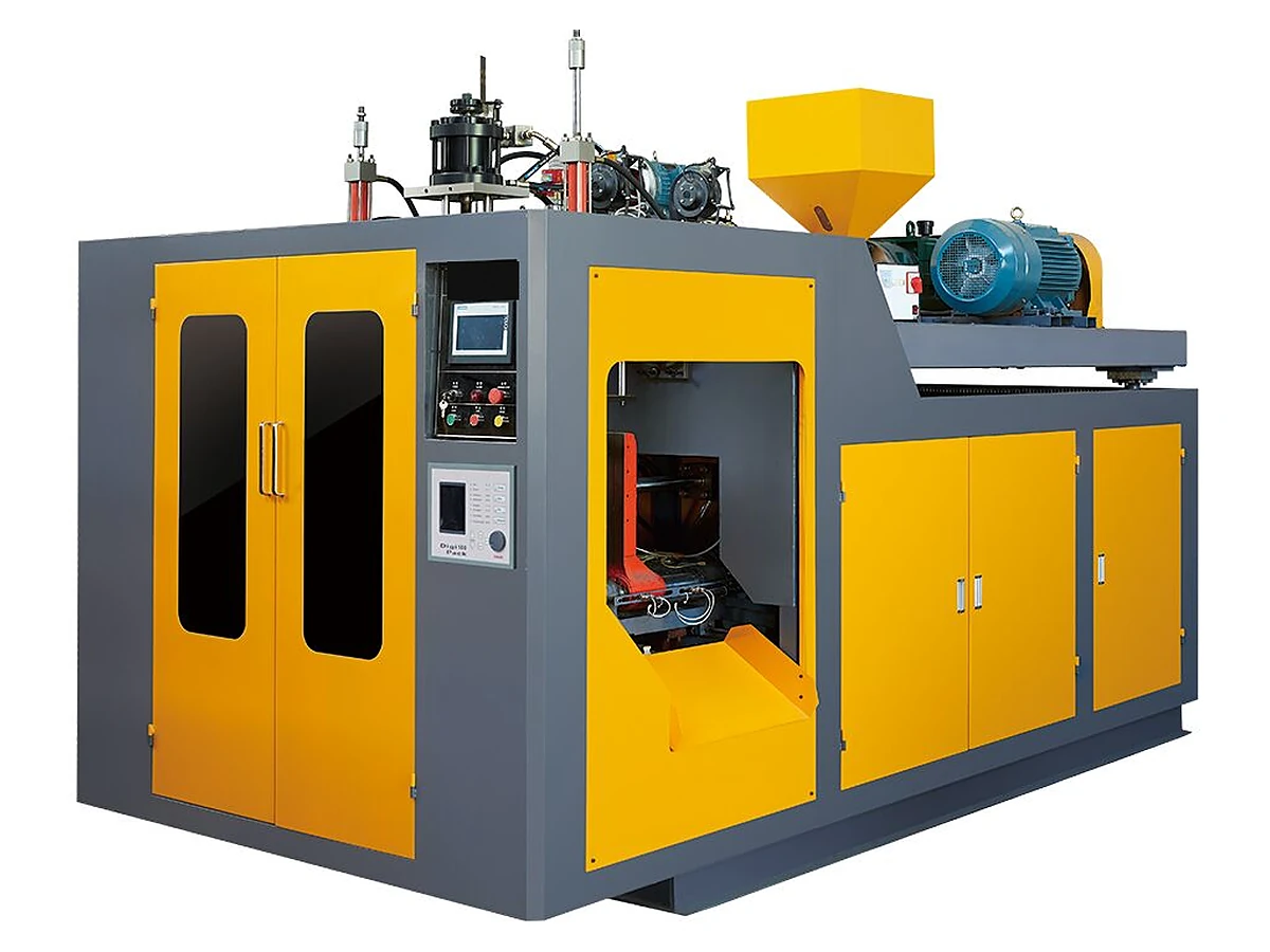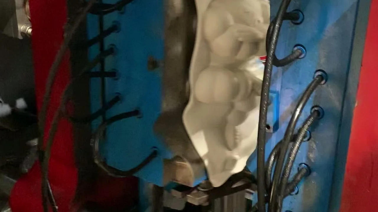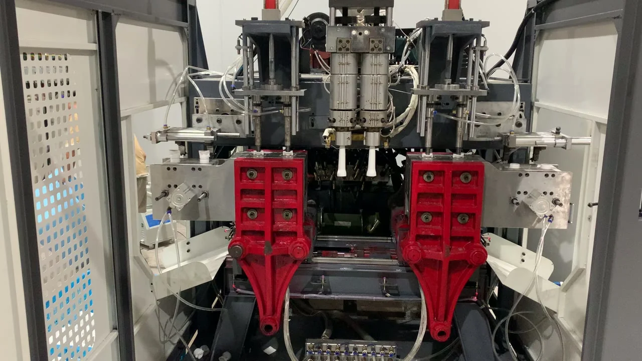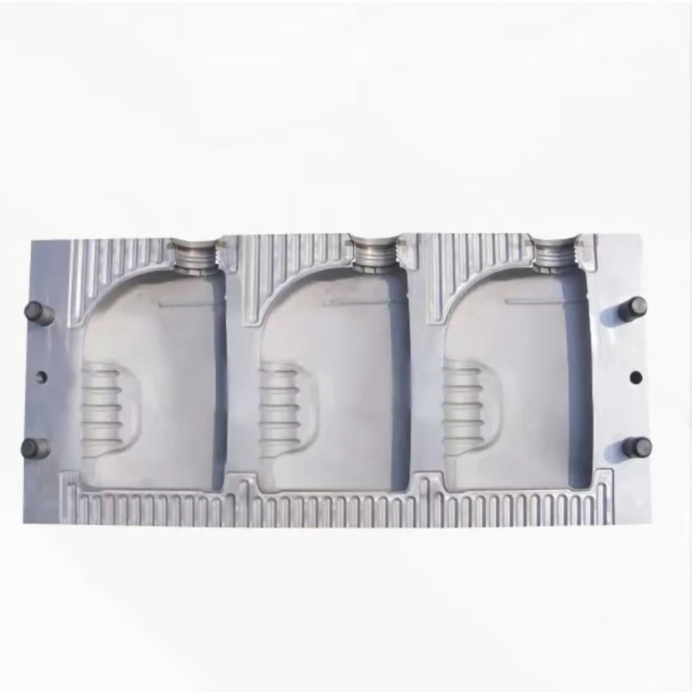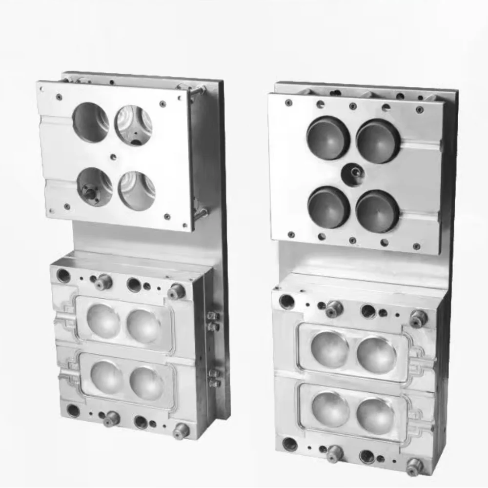
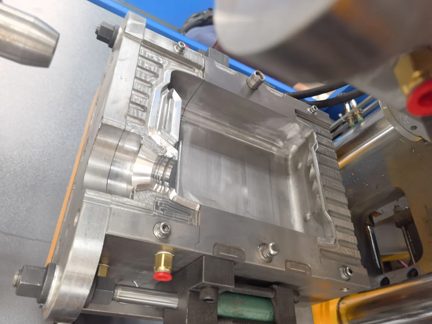
A new mold arrives crated, painted and apparently ready. The machine is on the floor, air and water are connected, and the only thing between you and sellable bottles is the installation. It is also where first-week problems are made: a mold seated slightly off-centre, clamped hard on one corner, or fed cooling water through the wrong port will run — with thick-thin walls, oval necks and short mold life. The sequence below is the one we walk through on a single-station machine, and every check ends with a pass condition you can see.
Nine steps from crate to first good part
Treat installation as a chain, not a list of tasks. Each step creates a condition the next one depends on: you cannot judge parallelism on a dirty platen, and you cannot judge wall thickness before the water circuit is leak-tested and the clamp force is set. The rule is: lift on the mold's lifting points, centre on the locating ring, verify the four corners, then connect water the way the drawing shows.
| Stage | What to check | Pass condition |
|---|---|---|
| Lifting | Sling on the mold's lifting points | Mold level, clear of tie bars |
| Seating | Locating ring into the platen bore | Base flush, no gap, mold number matches |
| Parallelism | Four-corner gap with the clamp closed | Even contact before final clamping |
| Clamp force | Projection area and blowing pressure | Mold-maker figure set, no flash at parting line |
| Water | Supply and return per drawing | Leak-free at working pressure |
| First part | Wall, pinch-off, neck, weight | Inside drawing tolerance, sheet signed |
Swipe the table to see all columns →
On a double-station machine, repeat every check on both stations before running either. The stations share one clamp frame, so an error on one side is usually a frame or seating problem, not a mold problem. If one side seats cleanly and the other does not, stop and check the platen faces before you touch the mold.
Lifting, centring and parallelism
Three checks decide most of what happens later.
- Lift only from the lifting points on the mold. Water fittings, blow pins and the parison path are not handles.
- Clean the platen and mold base before seating. A chip under the base tilts the cavity and loads one corner.
- Centre on the locating ring, which defines the machine axis — not on the outer edges of the mold.
- Check the four corners with the clamp closed, then re-check at working force; re-shim before you add force.
Water, air and the first-part sign-off
Cooling is the part of installation most often treated as plumbing. Circuit order, flow direction and air bleeding decide whether both mold halves run at the same temperature, and that shows directly in wall thickness and warp.
Connect supply and return exactly as the drawing shows. Baffled and bubbler circuits are directional; reversed flow can leave a hot spot that chiller capacity will not fix. Fill, bleed and leak-test at working pressure before the first dry cycle, and record the flow at each circuit.
- Wall thickness at base, body and shoulder — cut a part, do not judge by eye.
- Pinch-off: no thin line and no trapped flash.
- Neck: round, thread undamaged by the blow pin.
- Weight inside the drawing tolerance, flash trimmed clean.
- Parting-line flash even around the mold, not heavy on one side.
Only then sign the first-part sheet. Keep it with the mold, with the water-circuit record and the clamp-force setting, so the next changeover starts from known values instead of memory.
Still choosing the platform? Comparesingle- vs double-stationlayouts before the mold is built, and check the0.1–16 L single-station seriesplaten sizes against your mold base.
What to send for a quotation
Installation support is quoted against real parts, not a guess. Send these and the reply comes back with the right model and scope.
- Container drawing: volume, weight, neck and wall tolerance.
- Mold drawing or number, cavity count, mold weight and lifting points.
- Machine model, or the output you need per hour.
- Material and layer structure, including regrind.
- Site water, air and power: pressure, temperature, voltage, phase.
- Destination port and required delivery date.
Source: E-SHION product data. Specifications are subject to change without notice; customization is available.
This guide is written for production and procurement decisions. It uses published figures where available and avoids unverified performance claims.