A container can pass the weight check and still fail in the field: thin at the handle, thick at the base, leaking along the pinch-off. By the time the complaint arrives, the scrap is in the warehouse and the material is paid for. Wall-thickness variation is a costly defect in extrusion blow molding because it hides inside a part that looks correct.
Wall thickness variation: pattern first, profile last
The short answer: wall-thickness variation is rarely one fault with one cure. It is a distribution problem: the parison reaches the mold with more material in some places than others, or the mold and air move that material unevenly during blowing. The parison programmer can compensate for part of it, but using the profile to hide a mechanical or thermal fault usually moves the thin zone to another height — or another cavity.
A practical first rule: find where the thin zone sits and whether it moves. If the thin side shifts when the die is changed, treat it as upstream — die centering, die gap, temperature balance or parison sag. If it stays fixed to one side or one cavity, check clamping, blow-pin alignment and cooling before the profile. If the thin zone stays at the same height all around the body, check parison sag, die-head temperature and that part of the height profile. If bands repeat at a regular interval, look for a periodic mechanical or control action.
The four patterns and their likely causes
Describe what the operator can actually see, not the general term "uneven wall". The matrix below is a check order, not a diagnosis; confirm it against the mold drawing and a sectioned sample.
| Pattern | What you see | Check first | Check next |
|---|---|---|---|
| One side thin, opposite thick | Thin at several heights on one side | Die centering and die-gap concentricity; die-head temperature balance | Parison drop against mold center; blow-pin alignment |
| Thin at the top, thick at the base | Shoulder thin, base carrying extra material | Parison sag and drop timing; parison length against mold height | Top die-gap profile; die-head temperature stability |
| Periodic bands or rings | Rings repeat at regular spacing up the body | Screw speed and cycle stability; a repeating mechanical action | Die-gap profile points and controller response; parison guide contact |
| Thin at the pinch-off | Weak weld line, leakage or a thin strip at the parting line | Clamp force against mold projection area and blowing pressure | Blow-pin position and timing; mold closing and temperature |
Swipe the table to see all columns →
Measure the same points, the same way, every shift
The measurement method affects the conclusion more than the gauge. Agree the points with the mold designer: four clock positions at shoulder, body and base, plus the pinch-off line and neck. Mark them on the drawing, not the part.
- Cut a representative sample and measure the section with a micrometer; for production checks, use an ultrasonic gauge confirmed against a cut section.
- Record minimum, maximum and each location, not only the average.
- Measure every cavity, not only the first.
- Keep a signed golden sample and re-measure it with each new material lot.
- Log values by shift and material lot so a trend appears before the defect does.
The on-site check order that saves time
Once the pattern is confirmed, work in this order: material and heat history, die head, parison, clamp and air, cooling, profile. Changing several settings at once makes the result unreadable.
- Material and drying: confirm grade, lot and moisture handling. Contamination and moisture cause bubbles, holes and an unstable parison.
- Temperature: check barrel and die-head zones against the resin supplier's guidance, and confirm they are stable, not only on target.
- Die centering and gap: inspect concentricity and the gap around the die. An off-center die biases one side thin; correct it before trimming the profile.
- Parison sag: watch the parison from die to mold. Too long, too hot or unsupported, it thins where gravity pulls.
- Clamp and blow: check clamping force against mold projection area and blowing pressure, then blow-pin alignment and timing.
- Cooling: check mold temperature distribution and water flow. Uneven cooling distorts the part and changes the final wall.
- Profile last: adjust the programmer or die-gap profile only after the above are stable, one point at a time.
Change one variable at a time, let the machine stabilize, and measure the same points before and after. Record the material lot, ambient temperature and cooling-water condition with each trial; otherwise a slow drift can look like a profile improvement. Keep the trial short and repeatable; a change that only works on one part is not a fix.
What the take-off clip shows — and what it cannot
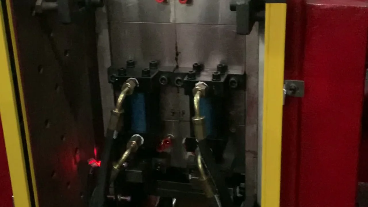
The clip shows the clamp, mold and bottle take-off sequence, which helps when a wall problem has to be described over the phone.
When you watch the clip or your own line, look at the parison before the clamp closes and the part as it leaves the mold. A parison that swings or arrives off-center, or a part that distorts on take-off, points to a machine or handling cause rather than a profile setting. The clip cannot measure wall thickness and is representative only.
Use it as a common reference with the team and the machine builder. If the motion differs from your machine, describe the difference in the enquiry; it is faster than putting "uneven wall" into words.
What to send for a quotation
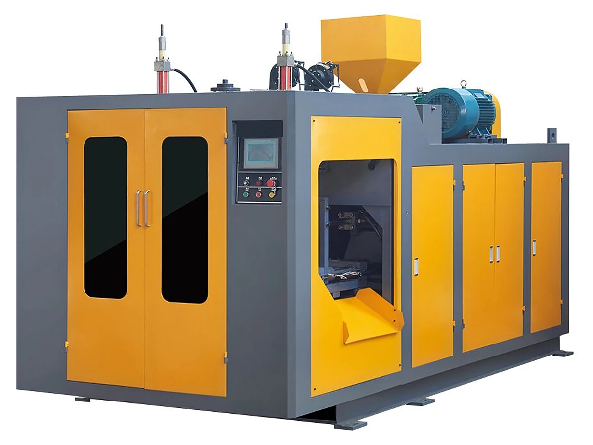
A wall-thickness problem is hard to describe in words. A useful quotation starts with the part and the measurements, not a list of settings. The reply should cover the machine configuration, the die head and parison-control option and, where relevant, the mold. Send the following so the answer is specific.
- Container drawing or 3D file, with wall-thickness target and critical zones marked.
- Material grade and supplier data sheet, plus any regrind or barrier layer.
- Current machine model, die-head type and parison-control arrangement.
- Existing mold drawing or cavity layout, if a mold already exists.
- Photos of thin and thick zones with a ruler and measurement points marked.
- Measurement records: minimum, maximum, height and clock position, by cavity.
- Target output, cavity plan and shift pattern.
- Destination voltage and frequency, and the inspection documents you need.
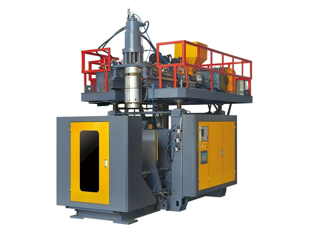
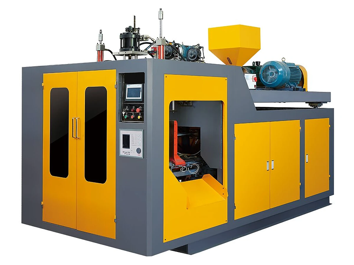
If the next step is a machine comparison, start with the 0.1–16 L single-station platform or the 20–50 L platform, and read how to choose an extrusion blow molding machine before fixing the cavity count. You can also send the files through the contact page.
The goal is not a perfect curve on paper. It is a part that holds its wall at the handle, the base and the seam, run after run, on the material you actually buy.
Source: E-SHION product data. Specifications are subject to change without notice; customization is available.
This guide is written for production and procurement decisions. It uses published figures where available and avoids unverified performance claims.