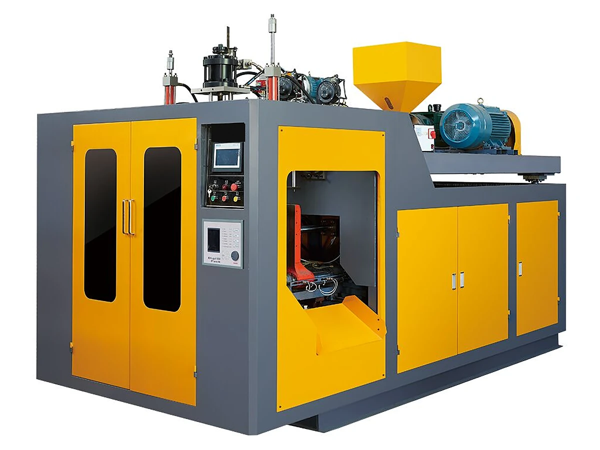
Wall thickness is where a blow molding project quietly gains or loses money. A few grams over target on every part becomes tons of material over a year; a fraction of a millimeter too thin at a handle corner becomes a leak or a failed drop test. The first instinct is often to blame the mold. Most of the time the answer is in the wall-thickness profile in the controller, the die gap it commands, and the parison before the mold closes.
1. Short answer: control the profile, not the average
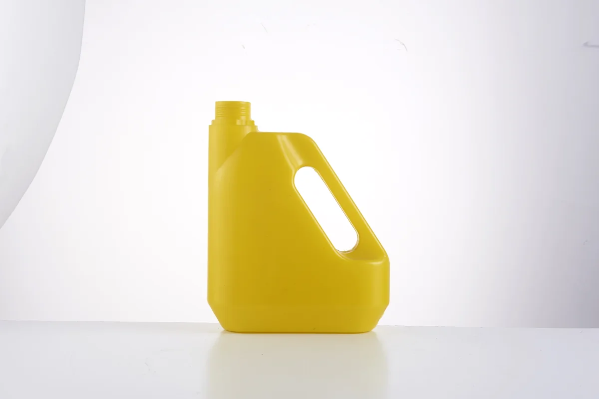
Wall thickness control is a profile, not one number. The controller steps the die gap through a sequence of set points as the parison is extruded, so each height of the container gets the thickness it needs: heavier at the pinch-off and the neck, leaner in the body panel. The working rule is to set the profile from the container's thickness map, verify it by weighing parts and cutting sections, then correct one variable at a time. If every cavity is thin in the same place, look at the head, temperature profile and curve. If only one cavity is thin, look at that cavity's die, air and cooling.
2. What the die gap is actually doing
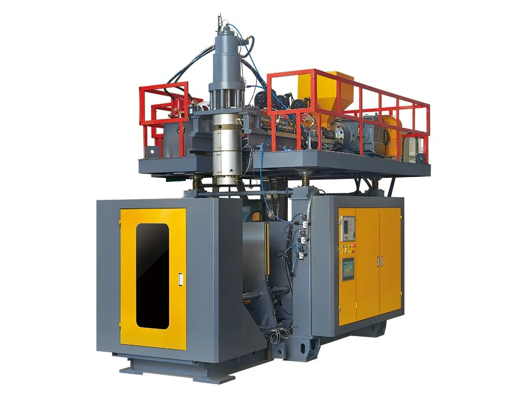
The parison leaves the head as a tube. Its wall thickness at any moment is set by the die gap — the annular opening between the mandrel and the die ring — and by how much the parison stretches under its own weight before the mold closes. A parison programmer stores a die-gap profile and moves the mandrel or die ring through it in step with extrusion, so the gap can be wide at the base of the container and narrow at the shoulder. Point count and head response depend on the controller and die-head design; confirm both for the model you are considering instead of assuming a number.
Three physical effects spoil a clean profile: uneven temperature around the head, an off-center die, and parison sag. If one side of the head runs hotter, the melt flows more easily there and that side runs thin. If the mandrel is off-center, the gap is unequal around the circumference, and the container comes out thin on one side and heavy on the opposite side. That pattern follows the head, not the mold, which is why changing the mold does not fix it. Sag stretches the hanging parison, so the upper part can end up thinner than the profile intended unless the curve compensates.
This is where lead, or advance, matters. The profile point that opens the gap has to act before that section of parison reaches the mold, because the melt takes time to respond and the parison keeps moving. Set the point too late and the correction lands at the wrong height; set it too early and the thick band sits above the target. The right lead depends on extrusion speed and controller response, so it has to be tuned on the machine. There is no universal value to copy from another plant.
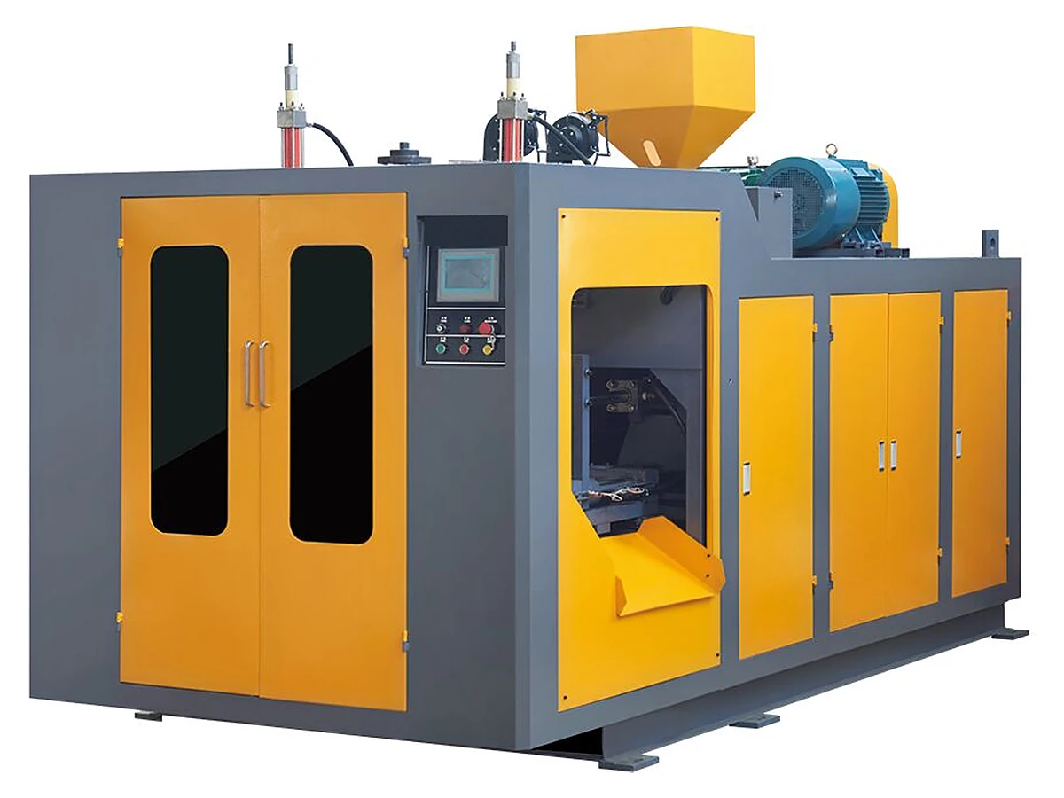
The ES-10LS is a 10 L model with a 110 kN clamp and 450 × 480 mm platens. Those are machine limits, not a wall-thickness guarantee — the profile still has to be proven on the mold. Compare the ES-10LS specifications with the 0.1–16 L single-station series, or look at the 20–50 L series for larger containers.
3. A field sequence that converges
Random adjustment is why this work can run long. Use a fixed order and change one thing at a time.
- Start from a stable process: melt temperature, head-zone temperatures and extrusion speed at the values that produced the last good part. A profile tuned on an unstable process will not repeat.
- Check die centering and die-gap condition with the head clean, and inspect the die lip before touching the controller.
- Run one cavity or one station, weigh every part and cut sections at the same heights. Record the thickness at each height, not an average.
- Correct the wrong zone with a small profile change, then re-run. Save the previous profile so you can step back.
- Copy the proven profile to the other cavities only after it holds on one, then check each cavity separately — a shared curve cannot correct a mechanical difference between cavities.
- Log the final profile, temperatures and part weight. That log starts the next mold; it is not a universal recipe.
4. Defects, causes and the first check
| Defect | Typical cause | Check first | Direction |
|---|---|---|---|
| Thin on one side, heavy opposite | Die off-center or uneven head temperature | Mandrel centering with a dial indicator; head-zone temperatures | Re-center, then re-profile |
| Thin base or pinch-off | Too little material at the bottom; low melt strength; short lead | Section at the weld line; parison length against mold close | Add material at the base; adjust lead; confirm melt temperature |
| Thick shoulder, thin body | Profile points landing early or late; parison sag | Where the thick band sits on the container height | Shift the profile timing; confirm extrusion speed |
| Bubbles or holes | Moisture or contamination; overheated melt | Material drying, regrind ratio, melt temperature | Dry or change material; lower the temperature |
| Weak pinch-off or leaking seam | Clamp force low for the projection area; blow timing; narrow weld land | Clamp force against mold projection area and blowing pressure; land condition | Adjust clamp and blow timing; check the mold land |
| Oval neck | Insufficient neck cooling; blow-pin misalignment; uneven wall | Neck cooling and blow-pin centering | Fix cooling and alignment, then re-profile |
Swipe the table to see all columns →
5. What to send for a quotation
Wall thickness is a mold-and-machine question, so the quotation is only as good as the inputs. Send:
- Container drawing or 3D file, with the wall-thickness map if one exists.
- Material grade, regrind policy and any multi-layer structure.
- Target part weight, minimum wall at critical points, and the test that defines a reject.
- Cavity count and station preference; the mold drawing if the mold already exists.
- Current profile, temperatures and section reports if the problem is on an existing machine.
- Destination voltage and frequency, and the air, cooling water and floor space available at the plant.
We will reply with the model, the die-head and controller configuration, and the points to confirm against the mold drawing. Where the drawing does not fix a value, the quotation says so rather than guessing.
For containers above 16 L, the 20–50 L production guide covers the mold and clamp checks. If you are still comparing platforms, read single-station vs double-station, or send the drawing through the contact page.
Source: E-SHION product data. Specifications are subject to change without notice; customization is available.
This guide is written for production and procurement decisions. It uses published figures where available and avoids unverified performance claims.