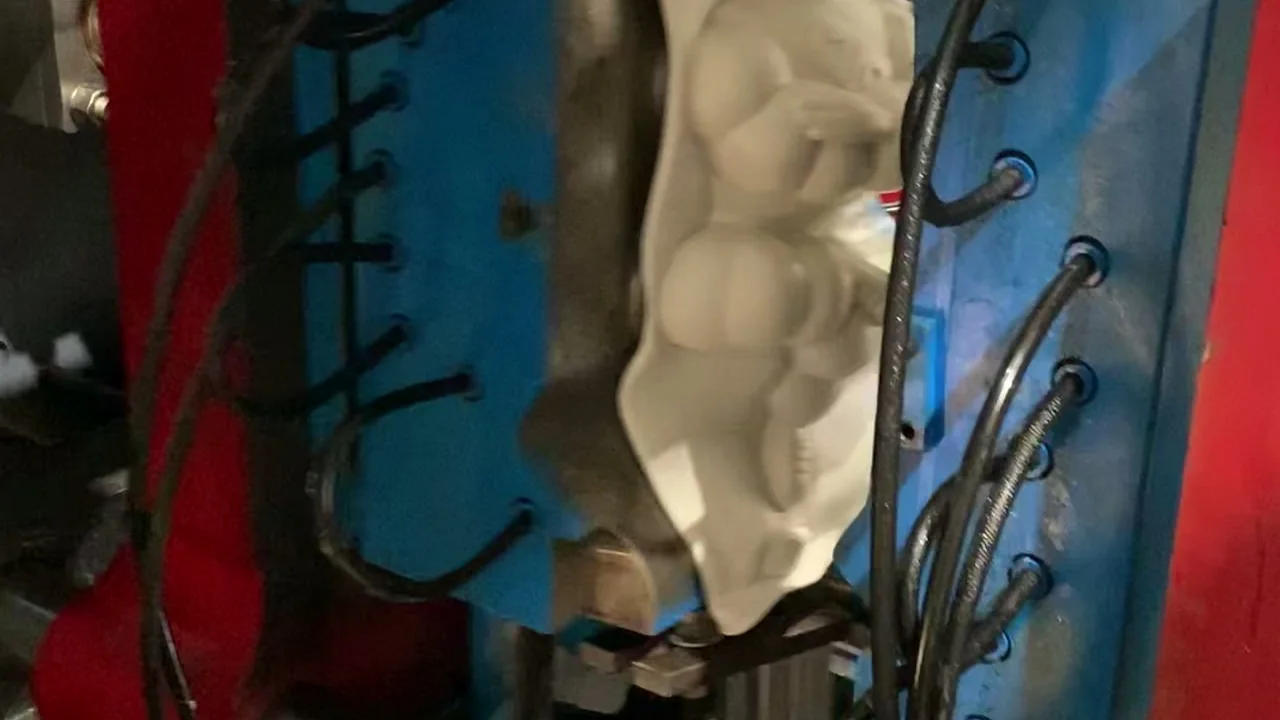
A bottle leaves the mold with a thin fin of plastic along the pinch-off, a ring of flash under the neck thread, or a skirt around the base. The reflex on the shop floor is to raise clamp pressure until the flash disappears. Sometimes it does. More often the flash moves to another spot, the frame starts to complain, and the trimming station still has the same workload. Flash is a sealing problem first and a tonnage problem second, and on many lines the tonnage was already correct.
What actually causes flash on a blow molded bottle?
Flash forms wherever molten plastic escapes a gap that should have stayed closed. The gap opens for two reasons: the separating force of blow air on the mold projection area exceeds the clamp's holding force, or the mold halves and inserts no longer meet cleanly at the shut-off, neck and base. Diagnose before touching the pressure valve.
The force balance: blow pressure times projection area
The mold behaves like a pressure vessel that opens along one plane. Blow air at 0.6 to 0.8 MPa pushes on the projected area of the container, meaning the silhouette you would see looking along the closing direction, with the neck and any handle included if they sit in that plane. Multiply the two and you get the separating force. Compare it with the clamp force and keep a margin, because the parison has stiffness, blowing can be off-centre, and clamp force is there to hold the mold shut, not to seal a shut-off that is already damaged.
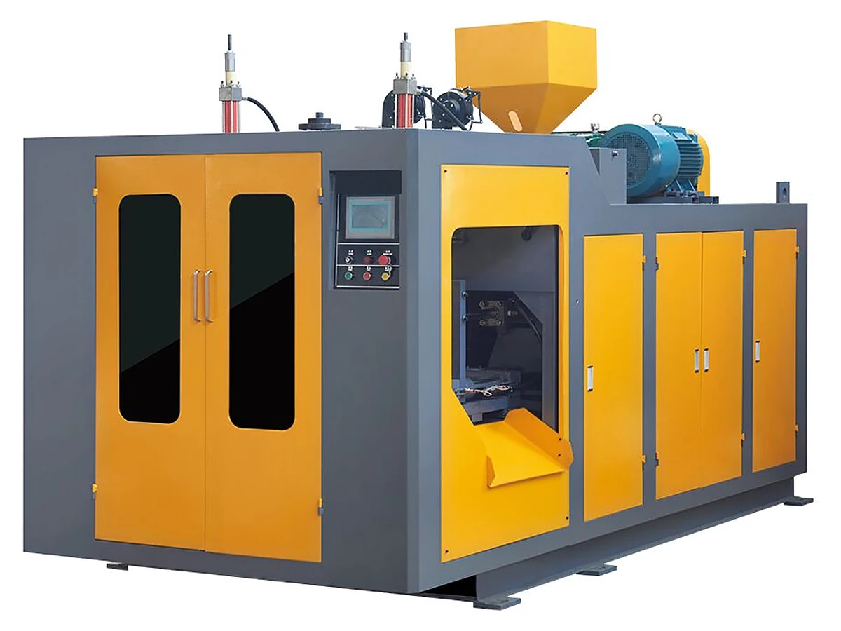
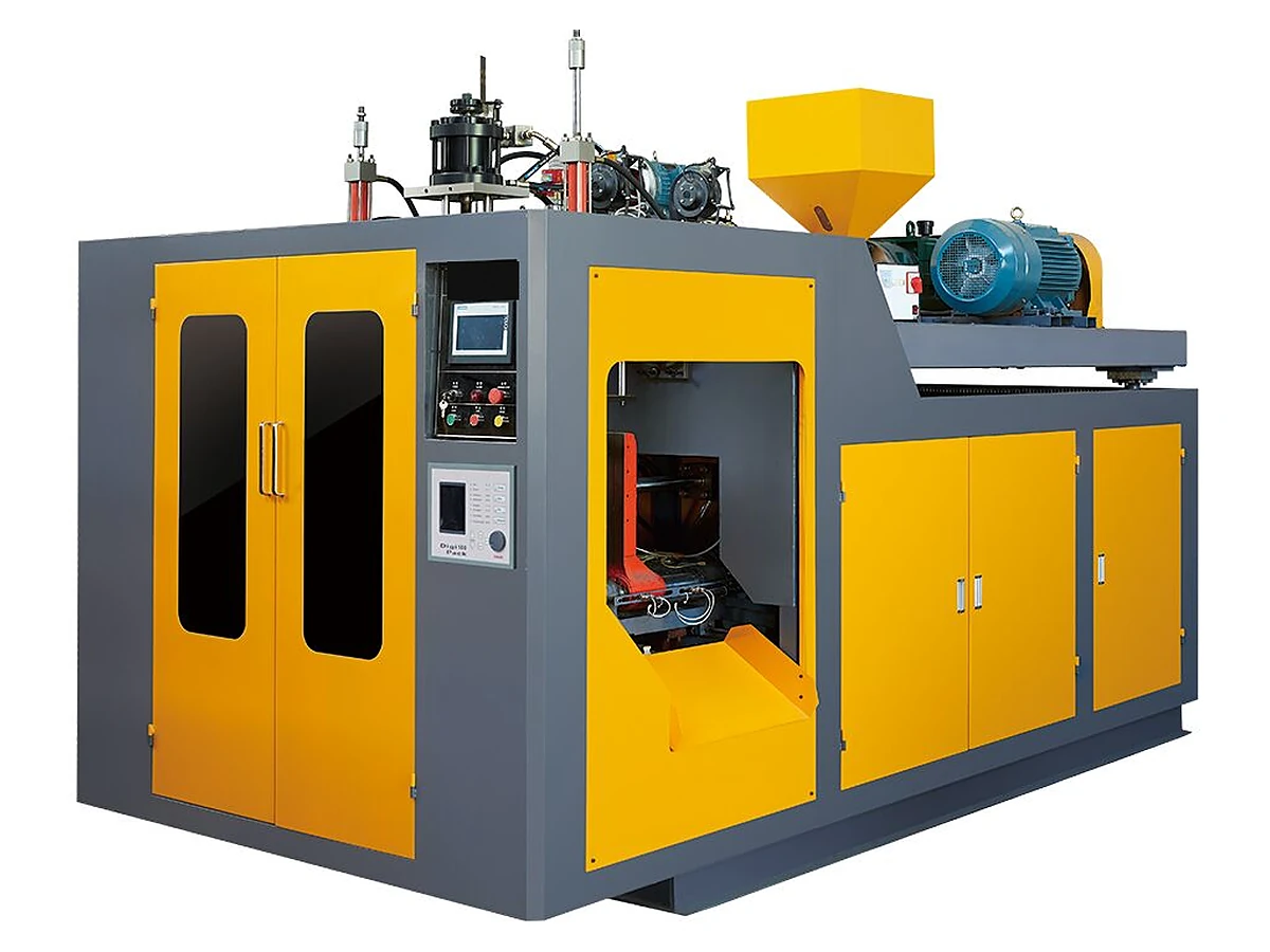
- Single-station ES-2LS and ES-5LS: 100 kN clamp force, platens 290 x 320 mm and 320 x 380 mm.
- Double-station ES-2LD and ES-5LD: 100 kN clamp force.
- ES-10LS and ES-10LD: 110 kN; the ES-10LS platen is 450 x 480 mm.
- ES-16LS and ES-16LD: 155 kN; the ES-16LS platen is 500 x 490 mm.
- ES-30L: 215 kN, platen 580 x 740 mm; ES-50L: 260 kN, platen 880 x 780 mm.
- Blow air on these models is normally set between 0.6 and 0.8 MPa; confirm the value on your process sheet.
A worked example makes the margin visible. Take an ES-10LS with its 110 kN clamp and a 10 L bottle with a projected area of about 0.045 square metres. At 0.8 MPa the separating force is 0.045 x 0.8 = 0.036 MN, or 36 kN, roughly one third of the clamp force. That is comfortable. Enlarge the same container to 0.09 square metres and the force doubles to 72 kN; the number is still under 110 kN, but platen deflection now matters. How much margin you need depends on mold support and shut-off width, so confirm it against the mold drawing instead of applying a fixed percentage.
The sizing logic behind these numbers is set out inhow clamping force is matched to a mold. If you are specifying a new machine, thesingle-station 0-16 L seriesand thedouble-station 0-16 L serieslist clamp force and platen size for every model.
Where the flash sits points to the cause
Before any calculation, look at the flash. Its position narrows the list of suspects faster than a pressure gauge. Work down the table: identify the location, check the cheapest item first, and only then consider the clamp setting.
| Flash location | Most likely cause | Check first | Does more clamp force help? |
|---|---|---|---|
| Around the neck thread or under the neck ring | Blow-pin not seated, worn neck insert, parison off-centre | Blow-pin alignment and stroke, insert wear, cutting ring | No, fix the blow-pin and insert |
| Along the pinch-off weld line | Worn, cracked or too-narrow shut-off land; thin clamp margin | Land width and wear, closing gap measured with a feeler gauge | Only after the land is checked |
| At the base seam or base insert | Mold not supported, base insert loose, platen deflection | Backing plates, insert fit, platen parallelism | No, support the mold first |
| A thin even fin all round the parting line | Separating force close to clamp force, blow pressure too high | Force calculation, actual blow pressure, clamp pressure setting | Yes, after the calculation |
| Only one cavity of a multi-cavity mold | Uneven mold height, one damaged shut-off, uneven load | Mold height across cavities, each land, platen parallelism | No, the mold is the problem |
| Flash with short shots or a weak pinch-off | Parison too short, sagging, or wrong temperature profile | Parison length and drop timing, die gap, temperatures | No, check parison and temperature |
Swipe the table to see all columns →
Mold, platen and parison checks, in order
Go through these before changing any pressure setting. Each item is cheaper than a damaged mold.
- Shut-off lands: measure the land width and look for a rounded, polished or cracked edge. A land worn round will not seal at any tonnage.
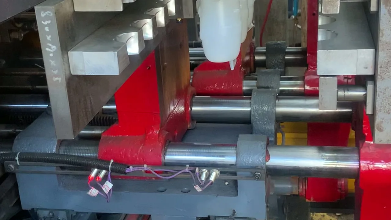
- Platen parallelism: with the mold closed, check the gap at four corners with a feeler gauge or dial indicator, and confirm the acceptable figure in the machine manual.
- Mold support: back the tool with plates that cover the loaded platen area, especially on single-cavity and large-container molds.
- Mold seating: both halves must sit flat and locate in the T-slots. A mold that rocks will flash on one side only.
- Mold height: on a multi-cavity tool, confirm that every cavity presents the same height to the platens.
- Parison: check drop length, swing and sag against the mold centre. An off-centre parison loads one shut-off harder than the other.
- Blow-pin: check alignment, stroke, seal and a clear blow hole. Neck-thread flash is usually a blow-pin or insert problem, not clamp force.
- Temperature profile: a cold parison will not weld at the pinch-off. Confirm the profile against the material data and a short trial.
- Clamp pressure setting: confirm the hydraulic pressure actually delivered agrees with the gauge and with the rated clamp force for the model.
Why adding clamp force can hide the real fault
Raising clamp pressure until the flash stops is tempting because it works for a while. On a worn shut-off it simply crushes the land flatter, which buys a few weeks and then leaves a mold that normal polishing cannot rescue. On a mold without proper support, the extra tonnage bends the platens further and the gap reappears somewhere else. On a hydraulic machine, running at the top of the pressure range raises oil temperature, which changes cycle times and shortens seal life. In every case the flash tells you the same thing after the adjustment: the fault has moved, not gone.
A useful trial is to slow the cycle and watch where the parison lands before the mold closes. If the parison is off-centre or its length varies between shots, fix the drop before touching the clamp. If it is centred and the flash is still even all round the parting line, the force calculation is the place to look.
If the gauge and the actual hydraulic pressure disagree, work throughhydraulic troubleshooting for blow molding machines. When you move from a 5 L bottle to a larger container, the12 L container production notescover the mold and clamp points that change, and theleak testing guideexplains why flash at the pinch-off often returns as a leak.
What to send for a quotation
- Container drawing or sample: volume, neck finish, weight and, if you have it, the projected area.
- Mold drawing or photos: cavity count, mold height, platen fixing dimensions and a close-up of the shut-off.
- Material and layer structure: HDPE, PP, PETG or a multi-layer configuration.
- Current machine and settings: model, rated clamp force, actual blow pressure, measured cycle time and where the flash appears.
- Output target: bottles per hour, shift pattern, and whether trimming is manual or automated.
- Site details: destination, voltage and frequency, compressed air supply and whether a chiller is available.
Source: E-SHION product data. Specifications are subject to change without notice; customization is available.
This guide is written for production and procurement decisions. It uses published figures where available and avoids unverified performance claims.