Two blow molding machines can share a clamp force, a screw diameter and a price band, yet one runs a 5 L jerrycan comfortably while the other fights every cycle. The difference is rarely the badge on the front door. It is how the machine is built: which die head forms the parison, how the clamp closes, where wall-thickness control acts, and how the bottle leaves the mold. Comparing quotations means comparing six systems.
What are the main parts of a blow molding machine?
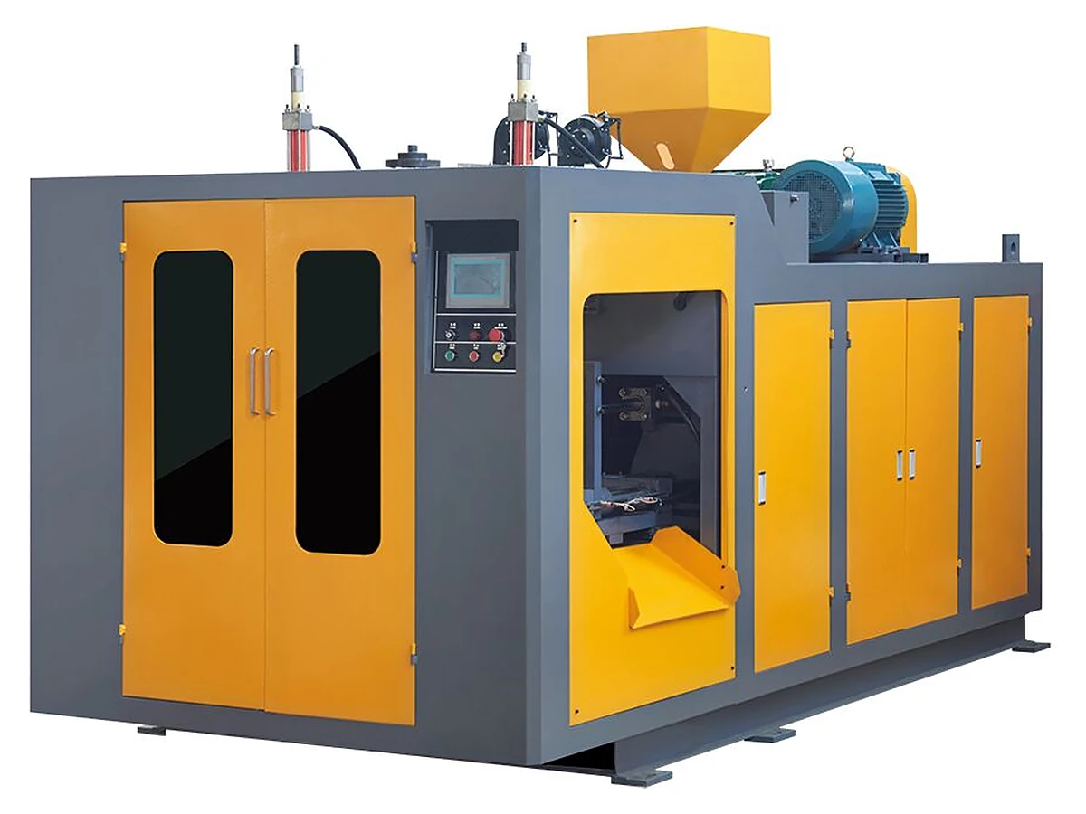
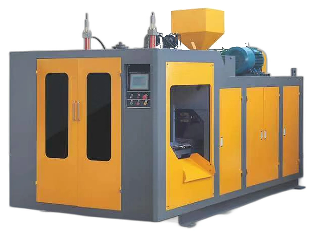
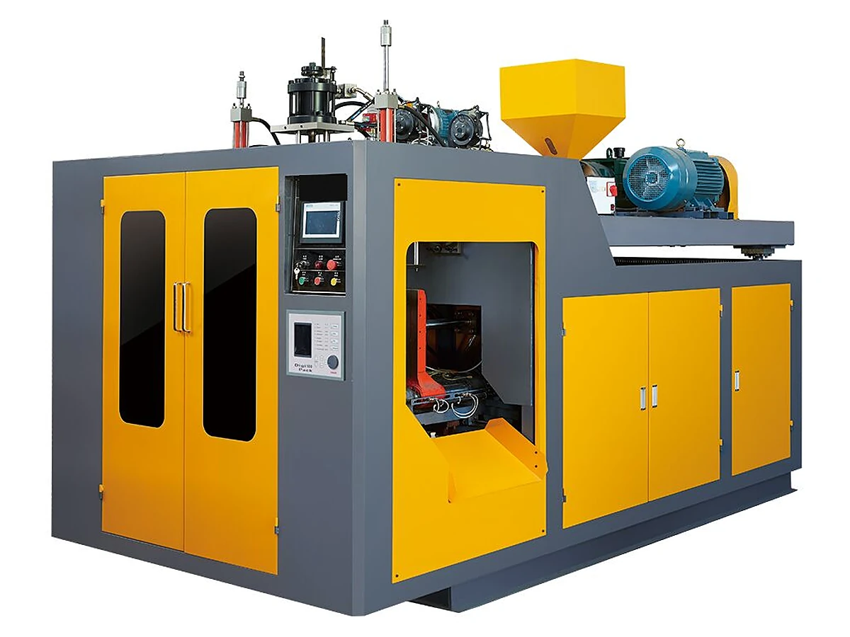
An extrusion blow molding machine has six working blocks: extruder, die head, clamp unit, blow unit, wall-thickness control and take-out. The extruder melts and conveys material; the die head forms the parison; the clamp holds the mold; the blow unit inflates; wall-thickness control profiles the parison; take-out removes the finished container.
- Extruder: screw, barrel and heaters plasticize the material and deliver a steady melt rate.
- Die head: turns the melt into a parison; die gap and centering set the wall distribution.
- Clamp unit: opens, closes and holds the mold against blowing pressure.
- Blow unit: the blow pin or needle admits air and forms the neck.
- Wall-thickness control: a parison programmer or die-gap profile varies thickness along the drop.
- Take-out: robot or manual extraction, deflashing and transfer to the next station.
The die head sets the machine's real range
The die head is where a machine's capability is actually decided. A continuous extrusion head forms the parison while the previous mold is still cooling, so small and medium containers run without waiting for an accumulator to charge. An accumulator head stores a measured shot of melt and pushes it out in one fast stroke, which is how very large, heavy parts are made. Industry references describe accumulator heads from about 1 kg to 240 kg of shot weight, and container ranges from 2.5 ml to 104 L across the wider market. That is a different class of machine from the 0.1–50 L band.
E-SHION's 0.1–50 L range normally uses continuous extrusion, and this page will not pretend otherwise. The ES-2LS to ES-50L models are built for bottles, jars, jerrycans and containers inside that band. A part that needs a 20 kg shot or a 200 L drum sits outside it and needs a different structure. We would rather say that before a quotation than after it.
Clamp, blow unit and take-out: where the cycle is won or lost
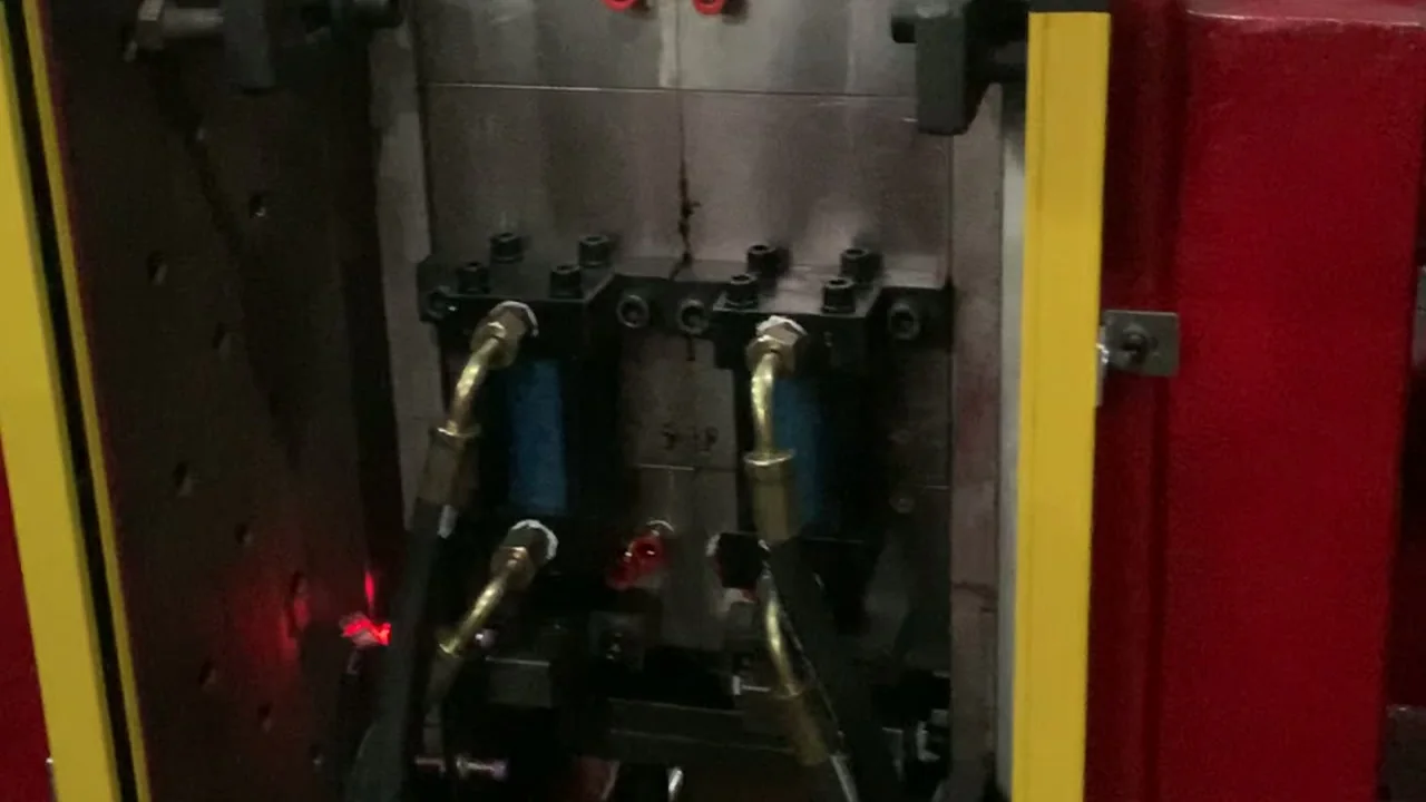
Clamping force is not a size badge. It must hold the mold closed against the blowing pressure acting on the mold's projected area, so a wide, flat container can need more force than a tall narrow bottle of the same volume. That is why the clamp is specified by force and platen size, and why a mold drawing matters more than a litre number when you compare models. The blow unit has to deliver stable air pressure and align the blow pin with the neck; misalignment shows up as oval necks and uneven flash. Take-out looks trivial until you run a hot, thin-walled part: grip it too early and you distort it.
Those three blocks are also where most selection mistakes start. Our guide towall-thickness controlexplains what the profile actually changes, and20 L chemical drum productionshows how the clamp and die head are matched to a heavier container. If you already have a mold drawing, send it through thecontact pageand we will check the clamp against it.
Clamping force and size from ES-2LS to ES-50L
| Model | Container size | Clamp force | Platen | Screw | Output | Installed power |
|---|---|---|---|---|---|---|
| ES-2LS | 2 L | 100 kN | 290 × 320 mm | 50–55 mm | 50–55 kg/h | 24–32 kW |
| ES-5LS | 5 L | 100 kN | 320 × 380 mm | 60–65 mm | 65–80 kg/h | 32–42 kW |
| ES-10LS | 10 L | 110 kN | 450 × 480 mm | 70–75 mm | 80–100 kg/h | 38–48 kW |
| ES-16LS | 16 L | 155 kN | 500 × 490 mm | 75 mm | 100–120 kg/h | 48–55 kW |
| ES-30L | 30 L | 215 kN | 580 × 740 mm | 80 mm | 100–120 kg/h | 100–110 kW |
| ES-50L | 50 L | 260 kN | 880 × 780 mm | 90 mm | 110–160 kg/h | 105–120 kW |
Swipe the table to see all columns →
Read the table as a starting point, not a verdict. Moving from the ES-10LS to the ES-30L changes the platen, the screw, the installed power and the machine weight, because the structure follows the container rather than the model name. A 10 L mold with a large projected area can still ask for more clamp force than its litre figure suggests, so the check is always projected area multiplied by blowing pressure, with a margin you can defend.
If you need more output in the same size band, thedouble-station 0–16 L rangeuses the same clamp figures with a different machine layout. The extruder's plasticizing capacity is the ceiling on output, not the station count alone.
Where wall-thickness control sits in the structure
Wall-thickness control is not a box bolted to the side of the machine; it is a function of the die head and the control that drives it. A parison programmer moves the die gap, or a servo axis moves the mandrel, so the parison is thicker where the container will stretch and thinner where it will not. Industry references quote up to 128 control points. More points give finer resolution, but the gain only appears when the die is centered, the melt temperature is uniform and the parison is not sagging.
On a 5 L jerrycan, the difference between a good profile and a poor one shows in the handle and at the pinch-off. On a 30 L container it shows up as weight variation between cavities. Ask for the number of points, the actuator type and the profile resolution, then ask to see a wall section from the same mold with the profile running. Without the section, the point count is only a number.
What to send for a quotation
A useful quotation starts with the container, not the machine. Send the following and the shortlist usually narrows to one or two models on the first reply.
- Container drawing: volume, neck finish, overall dimensions, wall thickness and any handle or insert detail.
- Material and layer structure: HDPE, PP, PETG or a multi-layer configuration, plus your regrind policy.
- Cavity count and target output per shift, stated as good parts rather than shots.
- Mold status: an existing mold with drawings, or a new mold quoted as a separate line.
- Plant limits: available power, compressed air, floor space, and destination country for voltage and documents.
Send the files to doris@e-shionmachine.com or through thecontact page. If you are still comparing machine types,when to add a second blow molding machineandblow molding OEM contract manufacturingcover the capacity and business side. Thesingle-station 0–16 L rangelists the models behind most of the numbers above.
Source: E-SHION product data. Specifications are subject to change without notice; customization is available.
This guide is written for production and procurement decisions. It uses published figures where available and avoids unverified performance claims.