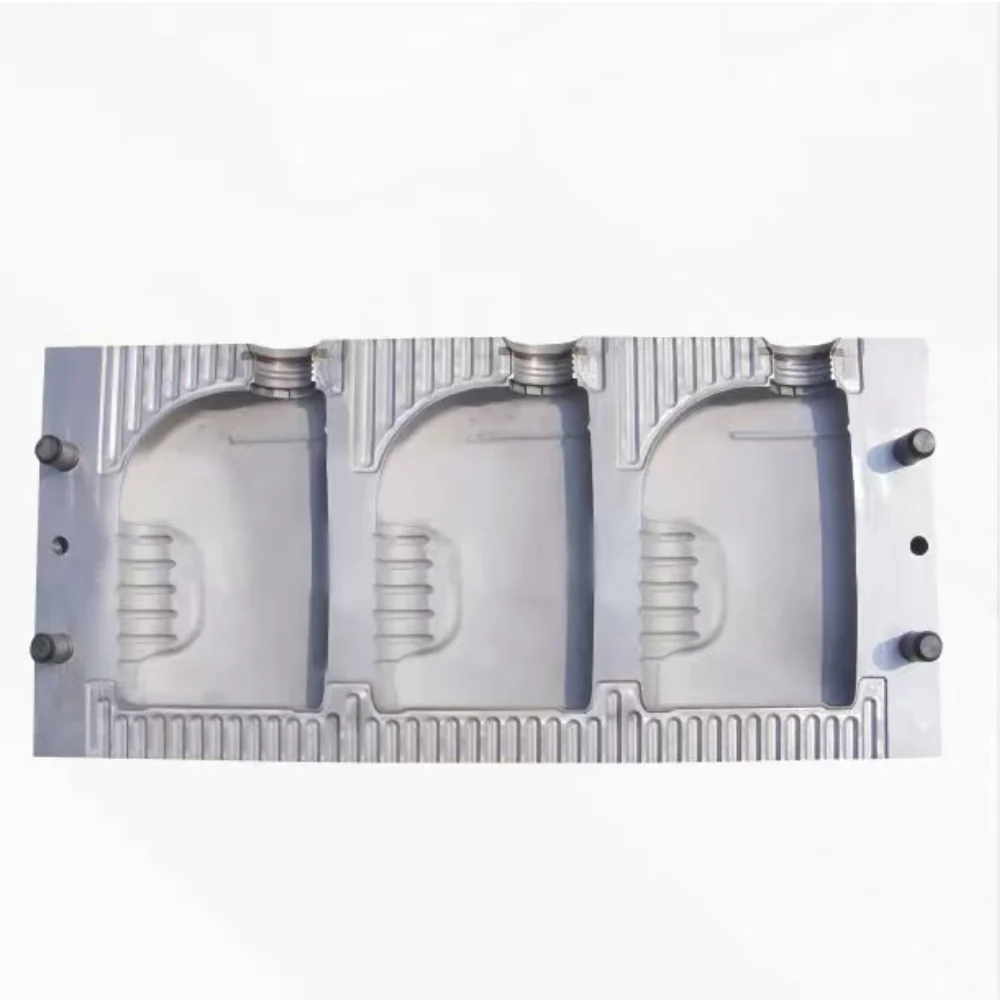
Your bottles come off the machine with a step at the parting line: one half of the mold sits higher, the trimmer leaves a lip, and the leak test fails on the thin side. The reflex is to blame the mold and wait weeks for a replacement. Most of the time the mold is the wrong place to start, and the step returns on the new tool.
The safe order: mold off the machine first
Check the mold halves on a bench first, then the guide pins and bushes, then the mounting faces, then platen parallelism with the clamp closed. Clamp force can hide a mismatch, so measure at the force you run. Flash is the symptom; the alignment number has to come from the machine drawing.
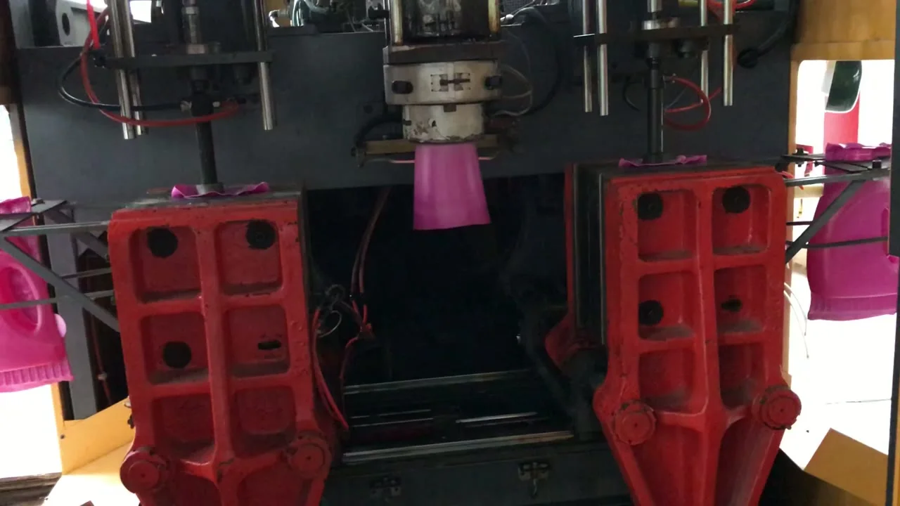
Two reasons for the order. A tool with worn guide pins sits crooked on any machine, so every later measurement inherits the error. And the clamp is strong enough to close a small gap by deflection: a burr under a mounting face, or a platen that is not parallel, gets pulled flat at full force. The step then hides with the clamp open and returns as a thin flash line.
- Mold halves off the machine: close by hand on a bench, check parting-line contact.
- Guide pins and bushes: measure wear, check bell-mouthing at the bush entry.
- Mounting faces: a 0.05 mm feeler gauge must not enter at any corner.
- Platens: parallelism checked with the clamp closed, at production force.
Bench checks: guide pins, bushes, mounting faces
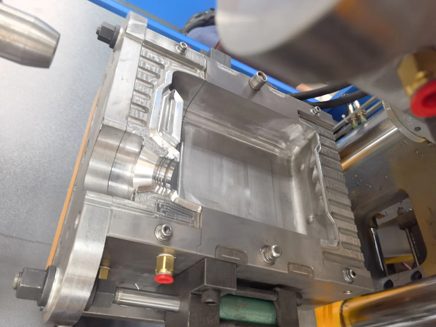
With the mold on a bench, close the halves by hand and run a 0.05 mm feeler gauge along the parting line. It should not enter except where the tool is relieved by design. If it enters at one corner but not the opposite one, the halves are not seating square: check the guide pins first. Measure each pin at the top, middle and bottom. A polished band, a taper or an entry step means a bent or worn pin; a bell-mouthed bush lets the halves shift.
Mounting faces get less attention. A chip, a burr, dried paint or rust under a clamp plate is a shim you did not intend, and it tilts the whole tool. Clean the platen and the mold back, stone off any high spot, and feeler-gauge all four corners at normal clamp torque. Then the impression-wire method: soft lead wire at four corners, closed at low force, measured with a micrometer. Equal thickness means parallel closure; unequal thickness shows which corner carries the load.
Platen parallelism and the numbers to check first
Platen parallelism is a machine property, checked last because the clamp must be closed to see it. Clean both platens, close at production force, repeat the wire test across the platen faces. Corner-to-corner thickness should sit within the tolerance on the machine drawing. That figure is not published here and must come from the drawing for your frame.
| Stage | Method | Tool | Warning sign |
|---|---|---|---|
| Mold halves on the bench | Feeler gauge along the parting line, closed by hand | 0.05 mm feeler gauge | Gauge enters at one corner only |
| Guide pins and bushes | Pin measured top, middle, bottom; bush entry checked | Micrometer, bore gauge | Polished band, taper or entry step |
| Mounting faces | Feeler gauge at four corners, mold back to platen | 0.05 mm feeler gauge | Gauge enters at any corner |
| Platen parallelism | Impression wire at four corners, clamp closed | Soft lead wire, micrometer | Thickness differs corner to corner |
Swipe the table to see all columns →
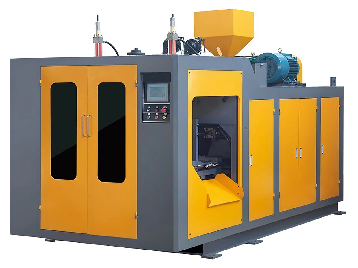
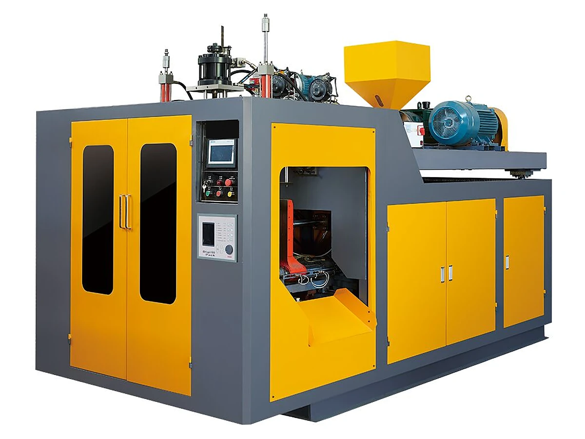
Before ordering a replacement tool, check the mold fits the frame. The ES-30L carries 215 kN of clamp, 350-800 mm of platen spacing and a 580 x 740 mm die plate; the ES-50L carries 260 kN, 400-1000 mm and 880 x 780 mm. Shut height, die plate width and mold weight must sit inside those figures.
Reading the symptom: which link is loose
Where the step appears is the fastest clue. Swap the mold to another machine: if the step follows the tool, the problem is in the mold or its guide pins. If it stays with the machine, look at the mounting faces and platens. If it changes with clamp force, suspect a high spot or a platen that is not parallel. If only one cavity shows it, check that cavity's insert and pin.
Take a case: a 5 L bottle shows a 0.3 mm step on the handle side, worse at the base. The mold is pulled and closed on a bench; the feeler gauge enters at one corner of the handle side, which rules out the extruder and the parison. That corner's guide pin shows a polished band and the bush is bell-mouthed, so the halves rotate as they close. New pin and bush, then a wire test, costs less than a new tool.
What to send for a quotation
Tell us the container and the fault, and we can point you at the right frame:single-station 0.1-16 L machinesordouble-station machines. If you are still comparing budgets, start with5 L machine price rangesandmold sourcing in Huangyan. For line layout, see5 L jerrycan production lineandparison wall thickness control. Photos and drawings go tocontact.
- Container: volume, a photo of the step, and which side it appears on.
- Mold: drawing or 3D file, cavity count, shut height, die plate size and weight.
- Machine: model, clamp force, platen spacing and the parallelism tolerance from the drawing.
- Readings: feeler-gauge results per corner, wire thickness at four corners, and the force used.
- Production: material, measured cycle time, and whether the step changes with clamp force.
- Spares: guide pin and bush part numbers, if you have them.
Source: E-SHION product data. Specifications are subject to change without notice; customization is available.
This guide is written for production and procurement decisions. It uses published figures where available and avoids unverified performance claims.