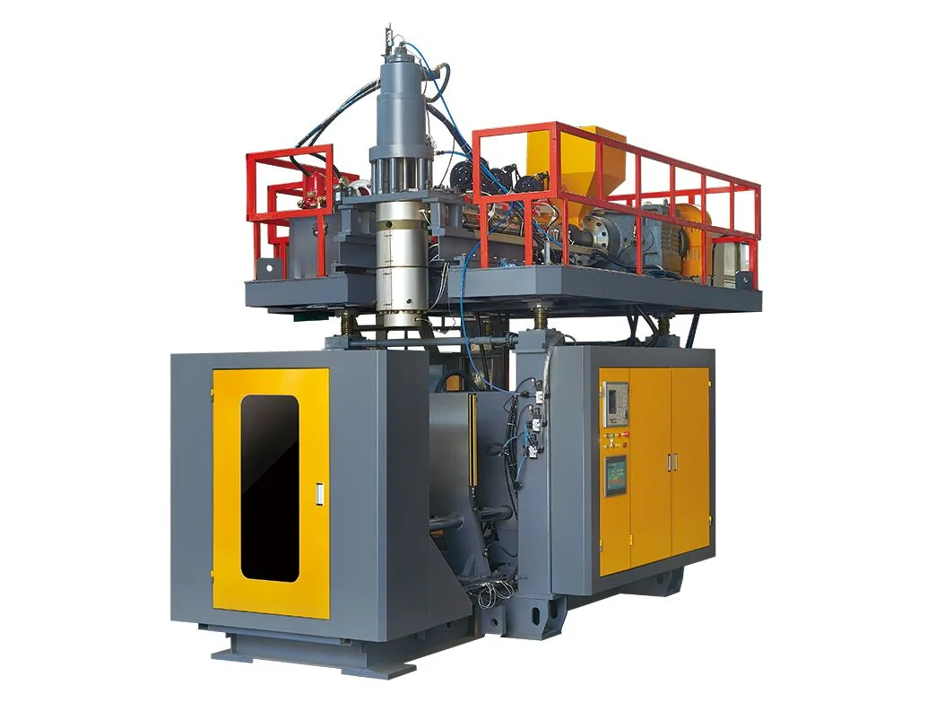
A one-litre pesticide bottle can pass every dimension on the drawing and still fail at the filler: the 63 mm neck ovalises under cap torque, the graduation reads a few millilitres off, or a base corner splits in the drop test. Pesticide packaging loads four requirements onto one container — a UN 3H1 design type, a closure-ready neck, legible metering marks and a solvent barrier — and the machine and mold must hold all four at production speed.
The short answer: neck, wall and barrier, in that order
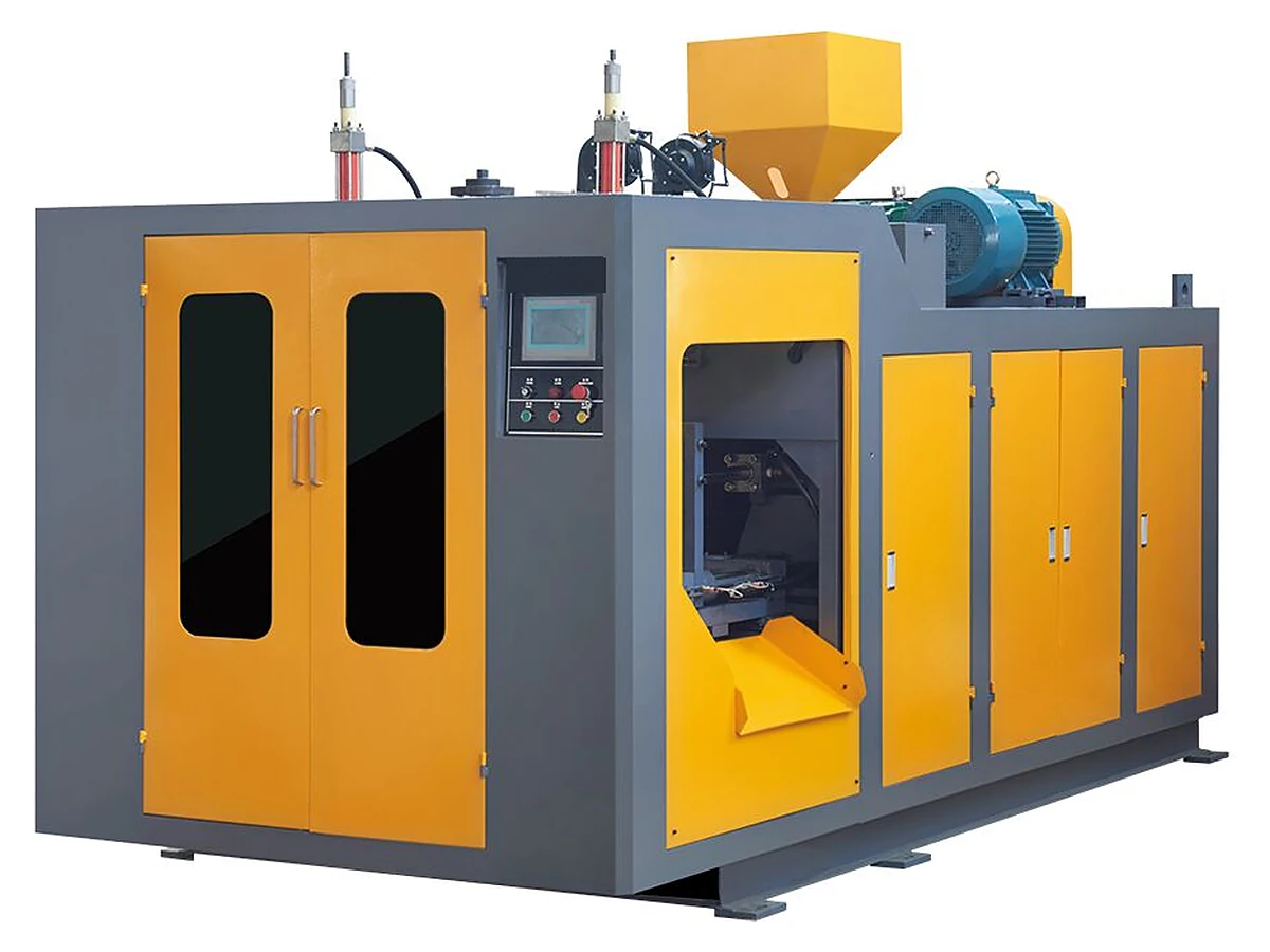
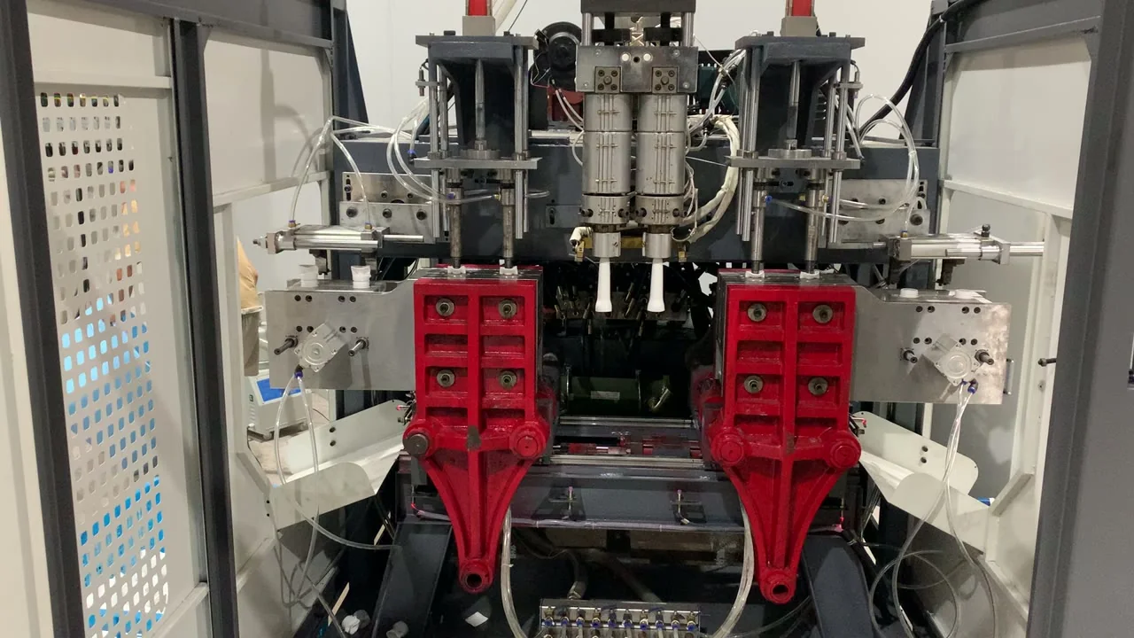
A 63 mm neck is a common agrochemical finish and can take child-resistant and tamper-evident closures, but the thread must match the closure drawing, not the nominal diameter. UN 3H1 is a design-type approval, not a machine certificate. For 1–5 L bottles, a 0.1–16 L double-station machine with 4–6 cavities is the usual starting point.
Start at the neck, because the closure is part of the test
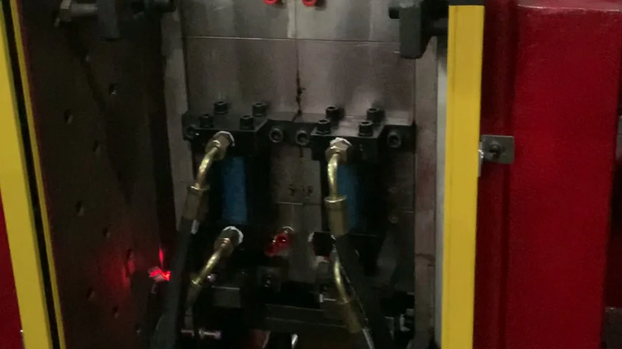
Agrochemical buyers often specify "63 mm" as if it were one item. It is a nominal diameter, and several thread and sealing geometries are sold under it. The drawing that matters is the closure supplier's: thread form, T dimension, sealing surface, neck ring and cap torque. A neck insert cut to a nominal 63 mm can accept a sample cap by hand and still leak on a filling line.
If the market requires a child-resistant closure, ISO 8317 is the test method the closure supplier and laboratory work to. It tests the closure and container as an assembly, so the bottle neck is part of the result. Tamper-evident bands add a second interface: the band must sit on the neck ring without binding or breaking in transit. Confirm both with the closure supplier and name the market in the enquiry.
Metering marks are cut into the mold, so their position is fixed with the drawing. Set each line at the fill volume the buyer uses, allow for shrinkage, and keep enough wall behind the mark for a crisp edge. Ask how the buyer checks graduation accuracy — at filling temperature, with a cylinder or by weight — and write that method into the trial report.
Solvent-based formulations add a permeation question that HDPE alone may not answer. Depending on the solvent, concentration and shelf life, the project may need a coextruded barrier layer or fluorination of the inner surface. If coextrusion is specified, the die head and layer structure become part of the machine scope. The structure is confirmed by the resin supplier against the formulation and filling conditions; no layer count should be fixed before that answer is in writing.
The resin side is covered inHDPE chemical compatibility, and the marking logic inUN 3H1 jerrycan production.
The requirement matrix to freeze before the mold
Six requirements drive the neck insert, the mold and the machine. Each is confirmed by a different party, so none can be settled by the machine quotation alone. Underneath them sits one production demand: wall thickness, pinch-off and the weld line must stay stable enough for the drop, leak, hydraulic and stacking tests your approval uses.
| Requirement | What it fixes | What the machine and mold must hold | Confirm with |
|---|---|---|---|
| UN 3H1 design type | The packaging code and performance level the filled bottle is approved against | Repeatable weight, wall map, neck and pinch-off matching the tested samples | Approval body or test laboratory in the destination market |
| 63 mm neck finish | Closure fit, sealing and cap torque | Neck insert dimensions, neck cooling, ovality and thread definition | Closure supplier drawing and production caps |
| CRC (child-resistant closure), if required | Child resistance and adult opening | A neck finish the closure can lock onto without over-torque | Closure supplier; ISO 8317 test laboratory |
| Metering graduations | Fill accuracy and legibility | Engraving position, shrinkage allowance and wall behind each mark | Buyer's fill volume and acceptance method |
| 1–5 L size range | Parison, die and clamp size | Clamp force against mold projection area; parison length and die gap | Container drawing and trial |
| Solvent barrier | Permeation and shelf life | Coextrusion layers or fluorination as specified; stable inner surface | Resin supplier against the formulation |
Swipe the table to see all columns →
Which machine, and how many cavities
Clamping force is set by the mold projection area multiplied by blowing pressure, not by container volume. A wide 5 L bottle can present more projected area than a tall narrow one. The published clamp figures are 100 kN for the ES-5LD and 110 kN for the ES-10LD, with 100–120 and 130–160 kg/h output bands and 320 × 380 and 450 × 480 mm platens. Confirm the projection area and blowing pressure before matching a model.
Output follows cavities × good parts per cavity per cycle × cycles per hour, where cycles per hour is 3600 divided by the measured cycle time. On a six-cavity layout with a measured 14 s cycle, that is about 257 cycles and 1,540 bottles per hour gross, before the good-part rate. On a double-station machine the extruder, not the second station, is the ceiling. Measure the cycle on your own mold.
Small-bottle experience is summarised in1–2 L bottle production; the0.1–16 L single-station rangeis the alternative when output targets are lower or the mold is simpler.
What to send for a quotation
A pesticide bottle quotation is only comparable when the neck, closure and barrier are on the table. Send these with the enquiry:
- 2D and 3D container drawings, including the neck finish, wall map, base and graduation positions.
- Closure drawing and supplier, the CRC requirement and the market that applies.
- Solvent or formulation type, fill volume and required shelf life, so the barrier can be confirmed with the resin supplier.
- UN code, dangerous goods, packing group, test standard and the approval body you will use.
- Output target in bottles per hour or per shift, cavity count and shift pattern.
- Resin grade, density, melt flow and the regrind ratio you intend to run.
- Plant data (power, compressed air, cooling water, floor space) and destination port.
Send the file through thecontact page, and check thecontract checklistandfloor space guidebefore the layout is fixed.
Source: E-SHION product data. Specifications are subject to change without notice; customization is available.
This guide is written for production and procurement decisions. It uses published figures where available and avoids unverified performance claims.