You have a bottle drawing, a mold quotation and a machine quotation on the desk, and the numbers do not match the sample you approved. Clamp force, screw diameter and output in kg/h are all on the sheet, yet none of them tells you where the wall will run thin, why the neck may come out oval, or whether the quoted output will survive a real shift. The answers sit in one cycle, from the die to the take-out conveyor, and in knowing what to watch at each step.
The short answer: seven steps, one cycle
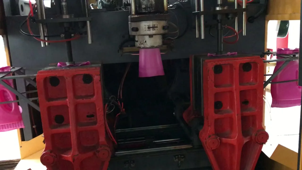
A bottle is made in one uninterrupted cycle. The extruder melts the polymer and forms a parison; the mold closes and pinches it; air inflates it against the cavity; the part cools; the mold opens; the bottle is ejected and trimmed. Wall thickness and cooling decide whether the result matches the drawing.
Step by step: what happens between die and conveyor
The order is fixed; what changes is how well each step is set. On a single-station machine the operator can watch the whole sequence from one position, which is why setup is usually learned here first.
- Melt and extrude. The screw plasticizes the granules and pushes the melt through the die head. Uniform temperature along the barrel and head matters more than one setpoint on the screen.
- Form the parison. The melt leaves the die as a tube. Its wall follows the die gap and the parison program, and it starts to sag as soon as it is free.
- Close and pinch. The two mold halves close on the parison and seal it at top and bottom. The pinch-off seam becomes the base and neck flash.
- Blow. Air enters through the blow pin and pushes the parison against the cooled cavity. The pressure must be enough to copy the mold surface, and the clamp must hold against it.
- Cool. The part gives up heat through the mold wall. Cooling is often the largest block of the cycle, and it is set by wall thickness and mold temperature control, not by blowing harder.
- Open and eject. The mold opens and the part leaves by hand, take-out robot or swing arm, depending on the line layout.
- Trim. Neck flash, base flash and handle flash are cut. Trimming can be in-mold or after take-out; the choice affects labor and the regrind loop.
Where the result is decided: wall, seam and cooling
Two settings decide more than any other whether the bottle passes: the parison program and the cooling. The program is a die-gap profile that changes the tube wall while the parison is extruded, thicker where the bottle stretches most and thinner where the blow ratio is low. It is set per mold and per material, and it is the first place to look when a wall runs thin at the base corner or the handle root.
Clamping is the next check. Force must be matched to the mold projection area multiplied by blowing pressure, with a margin, not to the container volume alone. A 5 L bottle with a large flat label panel can ask for more clamp than a taller, narrower 5 L container on the same machine.
| What you see | Check first | Usual adjustment |
|---|---|---|
| Thin wall at the base corner or handle root | Parison program and die gap | Reprofile the die gap; check sag and die centering |
| Oval neck or damaged thread | Mold close and blow-pin alignment | Check blow-pin centering, neck cooling and trim tool |
| Weak or stringy pinch-off seam | Mold close and pinch land | Check clamp force, pinch-land sharpness and parison position |
| Bubbles or holes in the wall | Extrusion and material | Check moisture, contamination, barrel temperature and screw speed |
| Parison curls or swings | Die head and temperature | Check die centering, temperature uniformity and extrusion rate |
| Part warps or sticks in the mold | Cooling and take-out | Check cooling time, mold temperature control and ejection |
Swipe the table to see all columns →
A worked example: from measured cycle to output
Take a hypothetical 1 L HDPE bottle in a four-cavity mold. A trial measures a 16-second cycle. Cycles per hour = 3600 ÷ 16 = 225. Good parts per hour = 225 × 4 × the good-part rate. At 96% that is 864 bottles per hour. Run the same mold at 18 seconds and the same rate gives 768, about 11% lost to two seconds of cooling. The figure worth negotiating is the cycle on your container, not a headline speed.
The same arithmetic explains the kg/h figure on a machine sheet. Extruder output in kg/h is plasticizing capacity, not bottle output. Bottle output is cavities × good parts per cavity per cycle × cycles per hour, and it is capped by how much material the extruder can melt in that hour. If the calculation demands more kilos than the extruder can plasticize, extra cavities will not help.
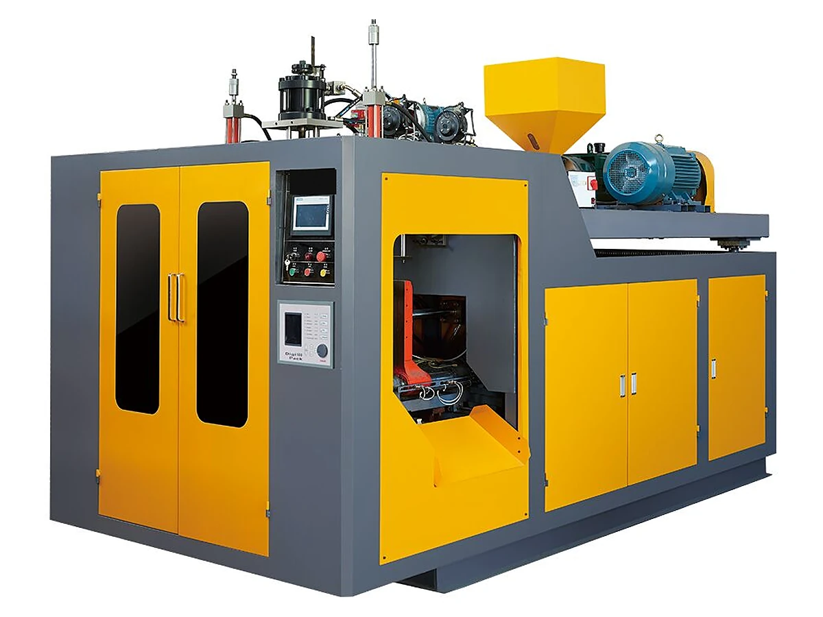
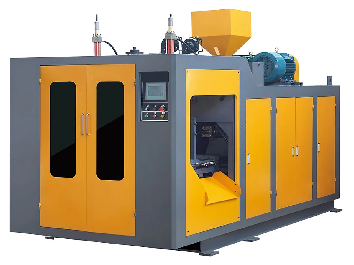
For scale, the ES-5LS platform is a 5 L single-station machine with a 100 kN clamp, a 320 × 380 mm platen and a published extruder output of 65–80 kg/h. Whether it fits your bottle is a question for the drawing: projection area against clamp, container height against the platen opening, and shot weight against plasticizing capacity. Confirm each point against the drawing and the quotation.
What to send for a quotation
- Container drawing: 2D with neck thread, sealing surface, handle and tolerance notes, plus a 3D file if you have one.
- Material and grade: PE, PP, HDPE, HDPP, PC, PVC or PETG, with the resin data sheet and any multi-layer structure.
- Weight and wall target: nominal weight, minimum wall at the base corner and label panel, and your test method.
- Output: bottles per hour or per shift, annual volume and planned shift pattern.
- Cavity layout you have in mind, or the annual volume if you want a recommendation.
- Destination: country, port, voltage and frequency, and any documents the import or filling line requires.
- Scope: machine only, machine with mold, or machine with mold and auxiliaries such as compressor, chiller, grinder and conveyor.
- A sample bottle or filled pack if the container exists, and the defects you want to avoid.
Send the files together and the reply can be specific: which model, what mold scope, and which points to confirm in a trial.
Start from the0.1–16 L single-station range, then readhow extrusion blow molding worksbefore you fix the cavity count.
Source: E-SHION product data. Specifications are subject to change without notice; customization is available.
This guide is written for production and procurement decisions. It uses published figures where available and avoids unverified performance claims.