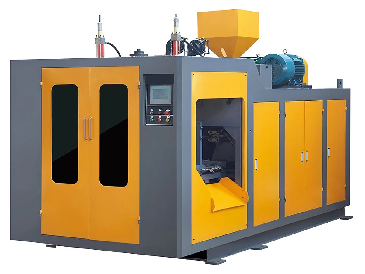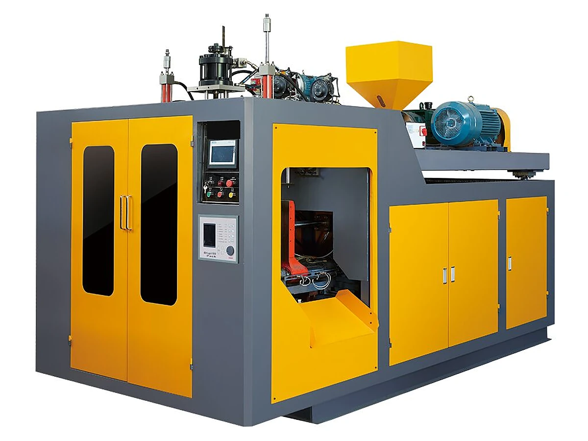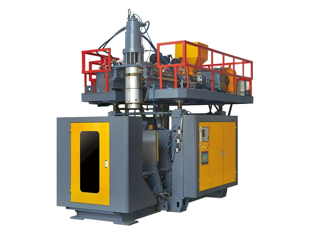
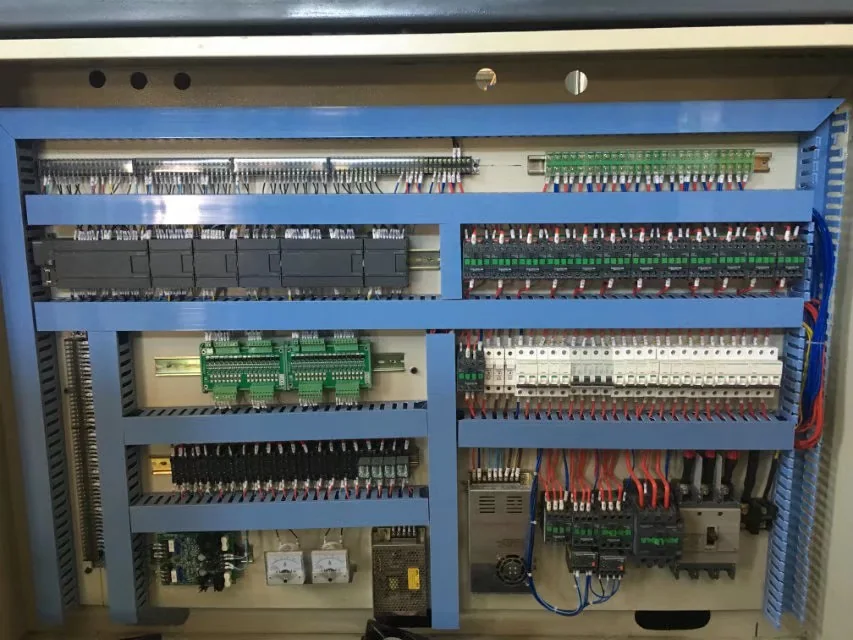
The mold is approved, the container is signed off, and the machine is booked into the export schedule in Huangyan. Then the electrician asks whether the building has 48 kW free, the rigger asks what the machine weighs, and the compressor supplier asks what flow the blow pin needs at 0.8 MPa. None of these questions can be answered once the crate is on the water. Site readiness decides whether commissioning begins the week the machine lands or several weeks later, and the delay is paid in idle labor, storage and a first shipment that misses its date.
The short answer: five site inputs gate the installation date
Five site inputs gate installation: floor and lifting capacity, power at the installed kW, compressed air at 0.8 MPa, cooling water, and destination voltage and frequency. Each is fixed at build or before packing, not at commissioning. Confirm all five before the order, and put installation scope, technician days and training in the contract.
The order of the checks matters. Destination voltage is an order-stage question, because the machine is wired for it at the factory. Floor loading and lifting are drawing-stage questions. Air and water can still be solved while the machine is in production, which is the right sequence.
Floor, lifting plan and the route into the building
Machine weight across the range runs from 3.5 t for an ES-2LS to 13 t for an ES-50L, and that figure starts two separate checks: what the floor carries in service, and what the lifting equipment can handle on the day. The floor check uses the foundation or general arrangement drawing and includes the dynamic load of the clamp, not only the static weight. No single foundation pressure figure fits every plant, because it depends on the model, platen load and your building; ask for the drawing and have a structural engineer confirm it.
- Machine weight and center of gravity taken from the general arrangement drawing, not from memory.
- Crane or forklift capacity at the actual lifting radius, not the nominal rating on the plate.
- Sling points, spreader beam and softeners, as marked on the machine frame.
- Door width, ceiling height, turning clearance and floor protection along the whole route.
- Final position marked on the floor, with clearance for mold changes, take-off and maintenance access.
Utilities: installed power, 0.8 MPa air and cooling water
Installed power is the sum of every heater, motor, fan and control load at full rating, and it is the number the supply, main breaker and cable are sized on. Across the single-station range it runs from 24–32 kW on an ES-2LS to 105–120 kW on an ES-50L. The 25:1 L/D screw and the barrel heating zones behind it are fixed at build; what you provide is the electrical capacity in front of them. Running draw is lower than installed power, but heat-up brings most heater zones on together, so sizing a transformer or generator on running draw is the classic site error.
| Model | Container size | Installed power | Machine weight |
|---|---|---|---|
| ES-2LS | 2 L | 24–32 kW | 3.5 t |
| ES-5LS | 5 L | 32–42 kW | 4.5 t |
| ES-10LS | 10 L | 38–48 kW | 6.5 t |
| ES-16LS | 16 L | 48–55 kW | 7 t |
| ES-30L | 30 L | 100–110 kW | 10 t |
| ES-50L | 50 L | 105–120 kW | 13 t |
Swipe the table to see all columns →
Air is the input most often confused with pressure. 0.8 MPa is a pressure, not a volume: the compressor must deliver the flow the machine consumes at that pressure, through a dryer and receiver sized for the line. Take the flow figure from the drawing instead of sizing from the receiver tank. Cooling water is the same story in reverse — temperature and flow together, not just a connection. If your plant water runs warm or the supply is intermittent, price a chiller with the project rather than after the first hot week.
FAT before packing, SAT after arrival
Two acceptance points protect the project. The factory acceptance test happens at Huangyan before export packing: the machine runs with your mold or a representative mold, the utilities are connected at the factory, and you or your agent witness the cycle and inspect the container. Record the settings, the measured cycle time and every open item. The site acceptance test happens after installation: the machine is leveled, connected, commissioned and run against the acceptance criteria agreed in the order. A machine that passed FAT can still fail SAT when site air or water is not what the drawing assumed, which is why the five inputs are checked twice.
A worked example: the five inputs for an ES-10LS
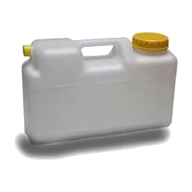
Take a 10 L HDPE bottle on an ES-10LS, single station. The machine weighs 6.5 t and draws 38–48 kW installed. The site file for this project holds five confirmations. First, the floor and foundation drawing, checked by a structural engineer for the 6.5 t static load plus clamp dynamics. Second, a lifting plan for 6.5 t plus spreader beam and rigging, at the crane's real working radius. Third, a supply at the destination voltage and frequency with 48 kW available to the machine alone, not shared with a press that runs all day.
Fourth, compressed air at the flow the drawing states. If the plant compressor is sized for hand tools, it will not hold pressure through a blow cycle, and the parison will show it before any gauge does. Fifth, cooling water at the stated temperature and flow, or a chiller sized for the line. Add the auxiliaries — compressor, chiller, grinder, conveyor — to the same project drawing, because they sit outside the machine price and are the items most often bought late. The check is not paperwork: each of the five has a drawing or a nameplate behind it and can be reviewed before the FAT.
What to send for a quotation
A quotation can only fix the installation scope when the site is described. Send these with the enquiry:
- Site plan with the machine position, door and ceiling dimensions, and the lifting route.
- Floor drawing or structural report, and whether a foundation or pit is planned.
- Supply voltage, frequency, phases and the capacity available for the machine.
- Compressed air pressure and flow, plus cooling water temperature and flow, or your chiller plan.
- Container drawing, resin, cavity count and output target per hour or per shift.
- Destination port and the import documentation you need.
- Whether installation, commissioning and operator training are wanted in the contract, and how many operators will be trained.
- Mold status: new tool or existing mold, and who supplies it.
Send the site file through thecontact page, and compare the0.1–16 L single-station rangeor thedouble-station platformbefore fixing the model, and walk thecontract checklistbefore signing.
Source: E-SHION product data. Specifications are subject to change without notice; customization is available.
This guide is written for production and procurement decisions. It uses published figures where available and avoids unverified performance claims.